


锆合金具有低热中子吸收截面、良好的抗腐蚀性能和力学性能等优点,是典型的水冷反应堆核燃料包壳材料[1]。先进沸水反应堆(ABWRs)和模块化反应堆(SMRs)以其设计紧凑、高燃耗和高安全性能而闻名[2],因此受到广泛关注。这一类反应堆的水环境中通常具有较高的溶解氧含量,会显著恶化含Nb锆合金的抗腐蚀性能。Zircaloys合金,如Zircaloy-2和Zircaloy-4,在含氧环境中表现出优秀的抗腐蚀性能[3~6],被广泛应用于沸水堆(BWR)[1,7],有望适用于ABWRs和SMRs。然而,高燃耗反应堆的发展对Zircaloys合金的抗腐蚀性能也会提出更高的要求。因此有必要开发具有更优异抗腐蚀性能的新型锆合金,并深入研究其在堆外的腐蚀行为。
合金元素含量的改变会对Zircaloys合金的腐蚀行为产生显著影响。Sn是Zircaloys合金中的主要合金元素,减少Sn含量可以提升Zircaloys合金的抗腐蚀性能。然而,当Sn含量低于1%时,会导致Zircaloys合金在沸水堆中抗腐蚀性能的降低[8]。Fe、Cr、Ni合金元素含量的适当增加,可以增强氧化膜的阻抗,使锆合金具有更好的抗腐蚀性能[9~11]。Garzarolli等[12]建议将Ni含量控制在0.03%至0.05%范围内,这有助于减少腐蚀过程中的氢吸收。综上所述,适当降低Sn元素并增加Fe、Cr、Ni元素的含量有利于提升Zircaloys合金的抗腐蚀性能。优化Zircaloys合金的热处理工艺,也可以提升其在高燃耗环境中的抗腐蚀性能。根据法马通公司(Framatome ANP)报道,在73 MWd/kgU的燃耗下,经过热处理工艺优化的Zircaloy-2合金表现出优异的抗腐蚀性能,该合金与德国BWR中使用的Zircaloy-2合金相比,在后期腐蚀加速阶段表现出良好的稳定性[13]。
综上所述,本文在传统Zircaloys合金的基础上,为了进一步提升锆合金的抗腐蚀性能,开发了一种Sn含量控制在较低水平的Zr-1.35Sn-0.22Fe-0.13Cr-0.05Ni合金,调整了热处理工艺并研究了热处理工艺对其显微组织的影响,同时也比较了该Zr-Sn-Fe-Cr-Ni合金和Zircaloy-4合金在360 ℃/18.6 MPa去离子水环境中的均匀腐蚀行为。
1 实验方法
实验材料为国产Zr-1.35Sn-0.22Fe-0.13Cr-0.05Ni合金和Zircaloy-4。合金管材的制备工艺为:真空电弧熔炼,β锻造,β淬火,热挤压,多次冷轧和α相区中间退火,形成外径9 mm、壁厚0.9 mm的成品管子,最后进行再结晶退火。累积退火参数A是指将β相淬火后在α相区重新加热的温度和时间进行归一化处理:
其中,ti 和Ti 是β相淬火后各次热处理的时间(h)和温度(K),Q为金属间化合物析出的激活能,R为气体常数,一般取Q/R = 40000 K[14]。累积退火参数的增大,意味着在α相区退火时间或温度的增加。所研究Zr-1.35Sn-0.22Fe-0.13Cr-0.05Ni合金热处理工艺对应的累积退火参数如下:Y1样品的累积退火参数为0.2 × 10⁻¹⁸~0.8 × 10⁻¹⁸ h,Y3样品的累积退火参数为1.1 × 10⁻¹⁸~1.5 × 10⁻¹⁸ h。实验样品被切割成长50 mm的小管,使用45% (体积分数) HNO3、45% (体积分数)去离子水和10% (体积分数)的HF进行酸洗处理,以获得粗糙度一致的表面。使用静态高压釜开展360 ℃/18.6 MPa的高温高压水腐蚀实验,实验标准参考ASTM G2M[15]。
为分析锆合金原始管材的显微组织结构,通过电子背散射衍射(EBSD)对锆合金的晶粒组织和微织构进行分析,实验所使用的设备为Oxford仪器Symmetry,其空间分辨率可达0.1 μm。为更好获得原始管材的晶体学信息,选用的扫描步长为0.2 μm,约为平均晶粒尺寸的1/10,扫描面积为90 μm × 128 μm。锆合金原始管材中第二相(SPPs)的分布情况主要通过扫描电子显微镜(SEM)对其第二相的粒径及分布情况展开分析,实验所使用的设备为Nova 400 Nano场发射扫描电子显微镜,其分辨率可达3.5 nm,可以清晰观察到原始管材中纳米尺寸第二相的分布情况。为进一步分析原始管材中第二相的分布、成分和结构,本实验使用配备有Super X型号能谱仪(EDS)的Talos F200S透射电子显微镜(TEM)对第二相的合金元素比例和结构展开分析。对于腐蚀后的样品,使用SEM观察氧化膜组织结构的演变和氧化膜内的裂纹演变,使用Zeiss Gemini 300型的SEM对腐蚀后氧化膜截面形貌进行观察,通过背散射电子(BSE)模式可以更清晰的观察氧化膜微结构的演变。腐蚀后金属-氧化物界面可以通过激光共聚焦扫描显微镜(LSCM)观察界面的起伏变化。LSCM可以快速高效完成亚微米级形貌和表面粗糙度的精确测量。本实验通过OLYMPUS LEXT OLS4000型LSCM获得了金属-氧化物界面的3D形貌,并通过该设备配备的软件获取金属-氧化物界面粗糙度。
2 结果与讨论
2.1 金属显微组织表征
图1
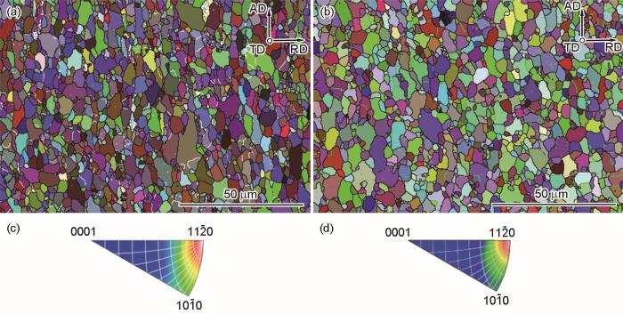
图1
原始管材AD-RD方向的晶粒取向分布图和AD方向的反极图
Fig.1
Grain orientation distribution maps (a, b) in AD-RD direction and inverse pole figures (c, d) in AD direction for Y1 alloy (a, c) and Y3 alloy (b, d)
表1 锆合金原始管材再结晶分数和小角度晶界占比
Table 1
| Alloy | Recrystallized fraction | Low angle grain boundaries |
|---|---|---|
| Y1 | 91.90% | 10.8% |
| Y3 | 92.80% | 10.5% |
由于Fe、Cr、Ni等合金元素在锆合金中的固溶度非常低,因此通常会在基体中析出形成第二相。图2是Y1合金和Y3合金基体组织中第二相的分布情况,可以观察到Y3合金中第二相的数目少于Y1合金。根据SEM图像进一步统计第二相的粒径和面密度,每种样品统计的第二相数目不少于1000个。结果表明,Y1合金中第二相粒径主要分布在50~125 nm,平均粒径约为118.4 nm,Y3合金中大尺寸第二相的占比明显增加,平均粒径约为144.7 nm,第二相的平均粒径随累积退火参数的增加而增加。Y1和Y3合金中的第二相面密度分别为1.1%和0.9%,面密度随累积退火参数的增加而下降。
图2
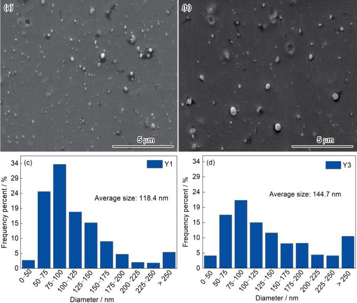
图2
Y1合金和Y3合金的第二相分布与第二相粒径统计图
Fig.2
Positional distributions (a, b) and particle size statistics (c, d) of second phase particles in Y1 alloy (a, c) and Y3 alloy (b, d)
通过TEM进一步分析第二相的形貌、成分和结构。如图3所示,第二相呈白色球状或椭球状,分布在Y1合金的晶界和晶体内部,部分第二相聚集成团,分布不均匀。Y3合金中,第二相主要分布在晶体内部,数量明显降低,呈弥散分布。结合EDS能谱进一步分析第二相中的合金元素成分,结果表明Y1合金和Y3合金中均存在两种不同成分的第二相,分别是Zr-Fe-Cr相和Zr-Fe-Ni相,其中Zr-Fe-Cr相占主导。进一步分析Zr-Fe-Cr相中的Fe/Cr原子比,分析数目不少于20个。如图4所示,Y1合金基体组织中Zr-Fe-Cr相的Fe/Cr原子比从0.6到2.2,而Y3合金中Zr-Fe-Cr相的Fe/Cr原子比更接近1。通过选区电子衍射(SAED)进一步确定第二相的结构,在Y1合金中观察到成分相同但结构不同的Zr(Fe, Cr)2相,分别为bcc结构和hcp结构,如图5a和b所示。在Y3合金中仅观察到hcp结构的Zr(Fe, Cr)2相,如图5d和e所示。热处理工艺的不同是导致Zr(Fe, Cr)2相结构差异的主要原因。Fcc结构的Zr(Fe, Cr)2为高温稳定相,通常在早期热挤压过程中形成,在经过α相区长时间退火后,基本可以转变为hcp结构[16]。Ni在锆合金中通常也会以第二相的形式存在,由于Y1合金和Y3合金中Ni含量很低,约为0.05%,因此其参与形成的第二相数目非常少,通过SAED进一步确定了该析出相在两种合金中均为bct结构的Zr2(Fe, Ni)相,如图5c和f所示。
图3

图3
Y1合金和Y3合金基体的高角环形暗场(HAADF)图像
Fig.3
High-angle annular dark-field scanning (HAADF) images of Y1 alloy (a) and Y3 alloy (b)
图4
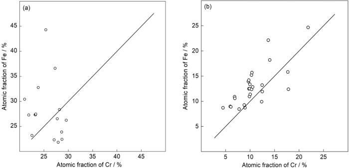
图4
Y1合金和Y3合金中Zr-Fe-Cr相的Fe/Cr比率
Fig.4
Atomic ratios of Fe and Cr in Zr-Fe-Cr phases of Y1 alloy (a) and Y3 alloy (b)
图5
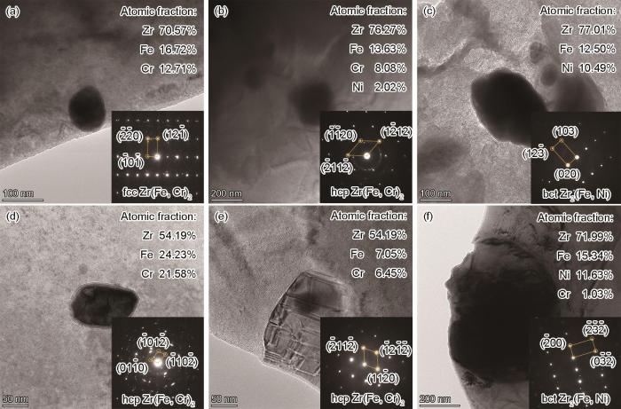
图5
Y1合金和Y3合金的第二相明场和选区电子衍射(SAED)花样
Fig.5
Bright-field images and selected area electron diffraction (SAED) patterns of second phase particles in Y1 alloy (a-c) and Y3 alloy (d-f)
2.2 腐蚀动力学
图6为样品在360 ℃/18.6 MPa去离子水环境中实验330 d的腐蚀增重曲线。3种样品在腐蚀初期呈类抛物线规律,Y1合金和Y3合金的腐蚀增重略高于Zircaloy-4合金。一段时间后,腐蚀速率发生突变,如图中箭头所示,定义此时发生腐蚀转折。腐蚀转折后,腐蚀速率迅速增加然后降低,进入下一个类抛物线循环。腐蚀转折前阶段可以使用类抛物线方程对腐蚀动力学曲线进行拟合,方程如(2)所示:
其中,kx 为氧化动力学常数,nx 为氧化时间指数。腐蚀动力学曲线拟合结果如表2所示。Zircaloy-4、Y1合金和Y3合金的nx 分别为0.35、0.32和0.33,初次腐蚀转折分别发生在160、220和250 d,转折时对应的腐蚀增重分别为35.6、43.2和45.0 mg/dm2。实验结果表明,Y1合金和Y3合金的初次腐蚀转折时间相较Zircaloy-4合金显著推迟。
图6
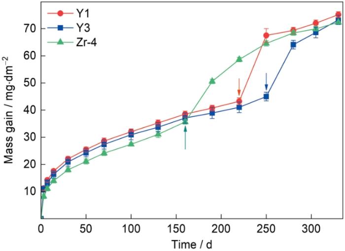
图6
锆合金腐蚀增重和时间关系图
Fig.6
Mass gain curves of Y1, Y3 and Zircaloy-4 alloys during corrosion in high-temperature and high-pressure water
表2 腐蚀动力学曲线参数
Table 2
| Sample | Corrosion mass gain at transition point / mg·dm-2 | Transition time / d | Kinetics law in the pre-transition region | R2 |
|---|---|---|---|---|
| Zircaloy-4 | 35.6 | 160 | 5.45t0.35 | 0.9984 |
| Y1 | 43.2 | 220 | 7.42t0.32 | 0.9983 |
| Y3 | 45.0 | 250 | 6.92t0.33 | 0.9983 |
2.3 氧化膜组织演变
图7~9展示了Y1、Y3和Zircaloy-4三种样品经不同腐蚀时间后形成的氧化膜截面SEM形貌。在所有的氧化膜中都观察到了裂纹,同时也观察到金属-氧化物界面呈现波浪状的起伏。腐蚀初期,氧化膜中可以观察到少量孤立横向裂纹,这些裂纹通常出现在金属-氧化物界面的凸起处,不会导致腐蚀速率的增加。随着氧化膜增厚,孤立裂纹的数目和体积逐渐增加,并且相互连接,形成带状裂纹,将氧化膜分成内外两层。带状裂纹的形成标志着腐蚀转折的发生[17,18]。在腐蚀250 d的Y1样品(图7d)和腐蚀305 d的Y3样品(图8e)中都观察到了带状裂纹。在腐蚀160 d的Zircaloy-4样品(图9b)中,可以观察到右边较厚的氧化物中形成了带状裂纹,为转折后区域,而左边较薄的氧化物中没有观察到带状裂纹,为转折前区域。这说明该区域为一个临界转折区域。初次腐蚀转折发生后,内层氧化膜厚度迅速增加,并在金属-氧化物界面附近形成新的横向孤立裂纹。在腐蚀305 d的Zircaloy-4样品(图9d)中,观察到第二层带状裂纹,这意味着第二次腐蚀转折的发生。在Y1、Y3和Zircaloy-4的各个腐蚀阶段的金属-氧化物界面下方,可以观察到一层白色氧化物的存在,一般认为该白色的氧化物是固溶氧层α-Zr(O)[19~21],其厚度随腐蚀时间的增加而增加,并在初次转折发生后迅速变薄。在Zircaloy-4氧化膜的临界转折区域可以观察到,从转折前区域过渡到转折后区域,α-Zr(O)的厚度逐渐变薄。这可能是初次腐蚀转折发生后,腐蚀介质渗透进入带状裂纹,加速了金属-氧化物界面的锆氧反应[22],使之前形成的α-Zr(O)快速氧化形成ZrO2。
图7
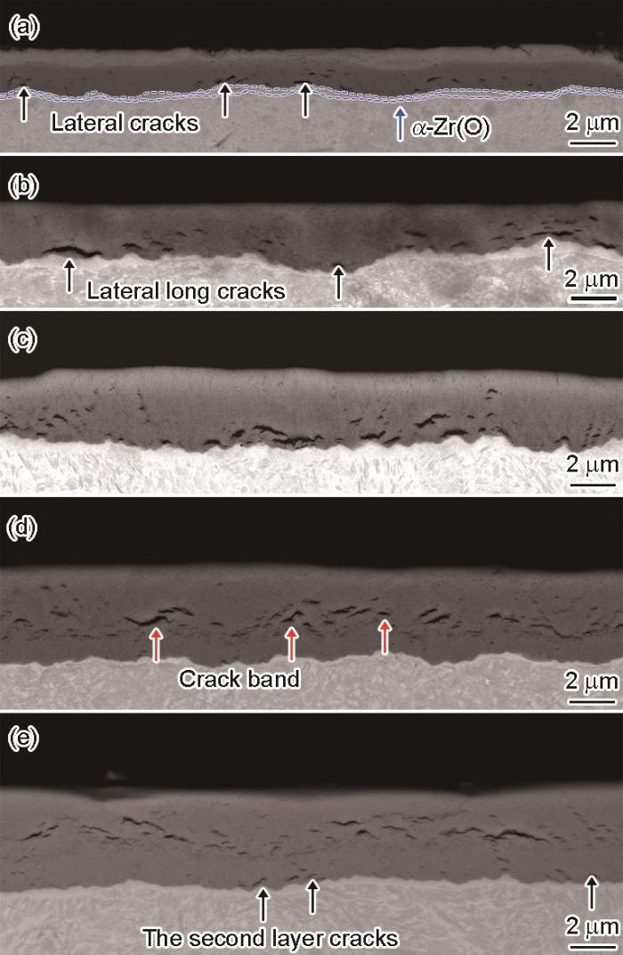
图7
Y1合金高温高压水腐蚀不同时间后的表面氧化膜截面形貌
Fig.7
Cross-sectional morphologies of oxide films formed on Y1 alloy after exposure in high-temperature and high-pressure water for 70 d (a), 160 d (b), 220 d (c), 250 d (d), and 305 d (e)
图8

图8
Y3合金高温高压水腐蚀不同时间后的氧化膜截面形貌
Fig.8
Cross-sectional morphologies of oxide films formed on Y3 alloy after exposure in high-temperature and high-pressure water for 70 d (a), 160 d (b), 220 d (c), 250 d (d), and 305 d (e)
图9
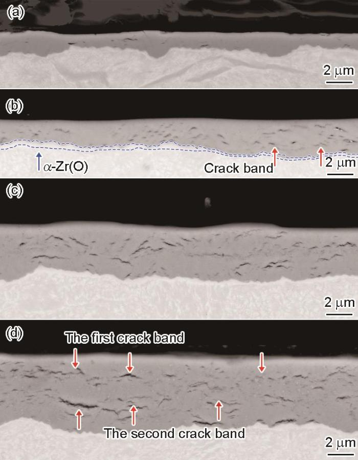
图9
Zircaloy-4合金高温高压水腐蚀不同时间后的氧化膜截面形貌
Fig.9
Cross-sectional morphologies of oxide films formed on Zircaloy-4 alloy after exposure in high-temperature and high-pressure water for 70 d (a), 160 d (b), 250 d (c) and 305 d (d)
金属-氧化物界面的波浪状结构与合金的腐蚀存在直接关系。Likhanskii等[23]认为腐蚀过程中,金属-氧化物界面附近的基体在氧化膜生长应力的作用下会发生蠕变,形成波浪状的结构,这有利于氧化膜内应力的释放。为进一步定量分析金属-氧化物界面的起伏情况,使用酸液将氧化后样品的基体腐蚀掉,然后取下完整的氧化膜,使用LSCM分析其内表面的起伏情况。Y1合金和Y3合金的金属-氧化物界面起伏三维形貌如图10所示。为了更直观的表现出腐蚀时间对金属-氧化物界面起伏的影响,使用OLYMPUS LEXT OLS4000附带软件得到了金属-氧化物界面的根均方高度(Sq)。Sq定义区域中各点高度的根均方,反映了各点高度的标准偏差。Sq的计算如下所示:
图10
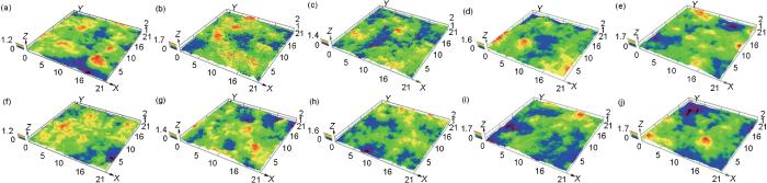
图10
Y1合金和Y3合金高温高压水腐蚀不同时间后的金属-氧化物界面三维形貌
Fig.10
3D morphologies of the metal-oxide interfaces of Y1 alloy (a-e) and Y3 alloy (f-j) after exposure in high-temperature and high-pressure water for 70 d (a, f), 160 d (b, g), 220 d (c, h), 250 d (d, i), and 305 d (e, j)
图11

图11
金属-氧化物界面Sq与腐蚀时间关系图
Fig.11
Sqvalues of the metal-oxide interfaces of Y1 and Y3 alloys as a function of corrosion time
2.4 讨论
实验结果表明,高累积退火参数的Y3合金比Y1合金表现出更好的抗腐蚀性能,具有更长的初次腐蚀转折时间。累积退火参数与锆合金的腐蚀行为存在密切关系,这主要因为累积退火参数的改变会对第二相的尺寸、数量和分布产生影响[10,12]。通过对原始管材显微组织的分析发现,Y3合金中第二相平均粒径有所增加,这被认为有利于提升锆合金的抗均匀腐蚀性能[25]。同时,Y3合金中第二相的面密度相比Y1也有所降低。这些高密度且尺寸较小的第二相会成为横向裂纹的形核位点,导致更高密度裂纹的形成,同时使锆合金具有更强的抗蠕变性能[26]。这可能会降低金属-氧化物界面的起伏,从而使氧化膜具有更高水平的内应力,加速带状裂纹的形成,影响腐蚀转折的发生时间。
Zr-Fe-Cr相作为主要分布在原始管材中的第二相,其氧化行为同样会对锆合金的腐蚀行为产生影响。第二相在金属-氧化物界面附近通常发生延迟氧化,与周围基体形成的氧化锆产生体积错配,导致这些第二相附近裂纹的形成[27~29]。然而并非所有的第二相附近都会形成裂纹,超过100 nm的第二相更容易导致裂纹的产生[27]。Y3合金中粒径分布在100~200 nm区间的第二相占比更高,这些第二相均匀的分布在基体内,随基体腐蚀被包裹到氧化膜中,在其上方或下方形成月牙形裂纹。这些细小裂纹有助于氧化膜内应力的释放[27,30],可以延缓氧化膜中裂纹的内联,延长带状裂纹的形成时间[26,27]。此外,Zr-Fe-Cr第二相中的Fe/Cr原子比同样对锆合金的抗腐蚀性能产生显著影响。腐蚀过程中,锆会在金属-氧化物界面反应生成氧化锆,形成的金属离子体积与金属原子体积的比被定义为Pilling-Bedworth比(P.B比)。Zr(Fe, Cr)2相在氧化膜中会逐渐氧化形成Zr和Cr的多晶或非晶氧化物,Fe则以金属的形式析出,其P.B比约为1.53,与氧化锆的P.B比1.51相接近[28]。Y3合金中第二相的Fe/Cr原子比更接近1,这有利于降低Zr-Fe-Cr相氧化诱发的体积错配导致的局部应力累积,减少其氧化过程中体积变化对氧化膜产生的二次破坏。
相比Zircaloy-4合金,Y1合金和Y3合金的初次腐蚀转折时间都有显著推迟,这可能与合金中Sn元素含量的减少有关。锆合金氧化过程中,会在金属-氧化物界面形成t-ZrO2和m-ZrO2,其中t-ZrO2主要分布在金属-氧化物界面,其形核和外延生长受到合金元素、晶粒尺寸、氧化膜内应力等多种因素的影响[31~33]。当远离金属-氧化物界面后,由于氧化膜内应力的降低,t-ZrO2会发生马氏体相变转变为m-ZrO2,并伴随体积膨胀。Sn是四方相稳定元素,有利于t-ZrO2的外延生长,Sn含量的增加会使金属-氧化物界面附近t-ZrO2的含量增加,导致氧化膜内相变水平的升高。马氏体相变导致的体积膨胀会增加氧化膜的内应力,一方面会造成更多的破坏性裂纹形成,另一方面会加速带状裂纹的形成,从而缩短腐蚀转折的时间[31]。值得注意的是,在腐蚀300 d后,Y1合金、Y3合金和Zircaloy-4合金都具有相似的腐蚀增重。然而,在腐蚀305 d的Zircaloy-4合金的氧化物中观察到第二层带状裂纹,而Y1合金和Y3合金的内层氧化膜中仅观察到少量孤立裂纹。这意味着Y1合金和Y3合金的初次和第二次腐蚀转折都显著推迟,但其长期抗腐蚀性能还有待进一步研究。
3 结论
(1) Zr-1.35Sn-0.22Fe-0.13Cr-0.05Ni合金的高温高压水腐蚀动力学曲线在转折点前表现出类抛物线规律,腐蚀增重略高于Zircaloy-4合金,但转折时间显著推迟,意味着降低Sn含量有利于延迟腐蚀转折的发生。
(2) 提高累积退火参数会对Zr-1.35Sn-0.22Fe-0.13Cr-0.05Ni合金中第二相的分布和成分产生影响。累积退火参数的增加会导致第二相平均粒径的增加,降低了样品中第二相的面密度,同时可以控制Zr-Fe-Cr相中的Fe/Cr原子比。
(3) 提高大尺寸第二相的占比,同时控制Fe/Cr原子比接近1,有利于延长初次腐蚀转折时间,提升Zr-1.35Sn-0.22Fe-0.13Cr-0.05Ni合金的抗腐蚀性能。
参考文献
Effect of dissolved oxygen in steam on the corrosion behaviors of zirconium alloys
[J].
Advanced boiling water reactors (ABWRS) show optimistic application prospect in the future. However, in these reactors, influence of dissolved oxygen (DO) on the corrosion rate of zirconium fuel claddings should be seriously considered. In this work, the effect of the dissolved oxygen (DO) on the corrosion behaviors of Zr-4, N18 (Zr-1.0Sn-0.3Nb -0.3Fe-0.1Cr) and N36 (Zr-1.0Sn-1.0Nb-0.3Fe) alloys in 400 ℃ and 10.3 MPa steam was investigated. A recirculation loop was used to control the DO level at about 0.1×10⁻⁶ and 1.0×10⁻⁶, respectively. The results showed that, under the two DO level conditions, N18 had almost the same weight gain as Zr-4 after exposure for 90 d, and N36 had the highest weight gain. In the initial period of the corrosion test, the three alloys had lower weight gain under higher DO level condition. With the increase of exposure time, the weight gain under 1.0×10⁻⁶ DO level exceeded gradually the weight gain under 0.1×10⁻⁶ level for each alloy, and the time needed for exceeding was significantly shorter for the alloy with higher Nb content.
蒸汽中的溶解氧对锆合金腐蚀行为的影响
[J].研究了400 ℃, 10.3 MPa蒸汽中, 溶解氧(DO)的存在对Zr-4, N18 (Zr-1.0Sn-0.3Nb-0.3Fe-0.1Cr)以及N36 (Zr-1.0Sn-1.0Nb-0.3Fe)合金腐蚀行为的影响, 采用微循环动水回路将溶解氧含量分别控制在0.1×10<sup>-6</sup>和1.0×10<sup>-6</sup>. 结果表明, 2种溶解氧浓度条件下, 腐蚀90 d后, N18合金的腐蚀增重与Zr-4合金的腐蚀增重接近, 而N36合金的腐蚀增重最高. 腐蚀初期, DO含量更高的条件下3种合金的腐蚀增重反而更低; 随着腐蚀时间的延长, 1.0×10<sup>-6</sup> DO条件下合金的腐蚀增重逐渐超过0.1×10<sup>-6</sup> DO 条件下的腐蚀增重, Nb含量越高的合金, 所需的时间越短.
Zirconium in the Nuclear Industry: Ninth International Symposium
[M].
Effect of dissolved oxygen on oxidation and hydrogen pick up behavior—Zircaloy vs Zr-Nb alloys
[J].
Zirconium in Nuclear Applications
[M].
4-Properties of zirconium alloys and their applications in light water reactors (LWRs)
[A].
Zirconium in the Nuclear Industry: Eleventh International Symposium
[M].
Zirconium in the Nuclear Industry: Twelfth International Symposium
[M].
Zirconium in the Nuclear Industry: Eleventh International Symposium
[M].
Zirconium in the Nuclear Industry: Eleventh International Symposium
[M].
Optimization of Zry-2 for high burnups
[J].
Effect of alloying elements and impurities on in-BWR corrosion of zirconium alloys
[J].
Review on correlation of accumulated annealing parameter and corrosion resistance of Nb-containing zirconium alloys
[J].
累积退火参数与含Nb锆合金耐腐蚀性能关系述评
[J].
Review of second phase particles on zirconium alloys (Ⅰ): Zircaloys
[J].
锆合金第二相研究述评(Ⅰ): Zircaloys合金
[J].
Analysis of the waterside corrosion kinetics of zircaloy-4 fuel cladding in French PWRs
[J].
Structure of zirconium alloy oxides formed in pure water studied with synchrotron radiation and optical microscopy: Relation to corrosion rate
[J].
Mechanism of the α-Zr to hexagonal-ZrO transformation and its impact on the corrosion performance of nuclear Zr alloys
[J].
ZrO phase embedded in the oxide of Zr-Sn-Nb-Fe-Cr alloy after corrosion
[J].
Untangling competition between epitaxial strain and growth stress through examination of variations in local oxidation
[J].Understanding corrosion mechanisms is of importance for reducing the global cost of corrosion. While the properties of engineering components are considered at a macroscopic scale, corrosion occurs at micro or nano scale and is influenced by local microstructural variations inherent to engineering alloys. However, studying such complex microstructures that involve multiple length scales requires a multitude of advanced experimental procedures. Here, we present a method using correlated electron microscopy techniques over a range of length scales, combined with crystallographic modelling, to provide understanding of the competing mechanisms that control the waterside corrosion of zirconium alloys. We present evidence for a competition between epitaxial strain and growth stress, which depends on the orientation of the substrate leading to local variations in oxide microstructure and thus protectiveness. This leads to the possibility of tailoring substrate crystallographic textures to promote stress driven, well-oriented protective oxides, and so to improving corrosion performance.© 2023. The Author(s).
Comparison on the microstructure, aqueous corrosion behavior and hydrogen uptake of a new Zr-Sn-Nb alloy prepared by different hot rolling temperature
[J].
Method of elastic energy minimization for evaluation of transition parameters in oxidation kinetics of Zr alloys
[J].
Focussed ion beam sectioning for the 3D characterisation of cracking in oxide scales formed on commercial ZIRLOTM alloys during corrosion in high temperature pressurized water
[J].
Zirconium in the Nuclear Industry: Twelfth International Symposium
[M].
Zirconium in the Nuclear Industry: 17th Volume
[M].
Origin and effect of lateral cracks in oxide scales formed on zirconium alloys
[J].
The corrosion of Zr(Fe, Cr)2 and Zr2Fe secondary phase particles in Zircaloy-4 under 350 oC pressurised water conditions
[J].
Oxidation behaviour of zirconium alloys and their precipitates-A mechanistic study
[J].
Zirconium in the Nuclear Industry: 18th International Symposium
[M].
Critical behavior of interfacial t-ZrO2 and other oxide features of zirconium alloy reaching critical transition condition
[J].
Research on the existence and stability of interfacial tetragonal zirconia formed on zirconium alloys
[J].
