


索承式桥梁拥有比其他类型桥梁结构更加优越的跨越性能,是大跨径、超大跨径桥梁工程的优选桥型,在世界范围内建造广泛。拉 (吊) 索是索承式桥梁主要的受力构件之一,拉 (吊) 索的性能往往决定索承式桥梁的安全性和耐久性,拉 (吊) 索是由数根平行钢丝或钢绞线组合而成。随着大量调查研究表明,世界上许多索承式桥梁存在拉 (吊) 索老化的问题,拉 (吊) 索内的钢丝可能存在初始裂纹等缺陷或投入运营后受到周围腐蚀环境的长期侵蚀,在服役过程中交变应力的作用下,钢丝初始裂纹或蚀坑进一步扩展,甚至导致拉 (吊) 索发生断裂,如重庆鹅公岩轨道大桥吊索断裂事故。
腐蚀环境对拉 (吊) 索的影响主要表现为拉 (吊) 索内部钢丝或钢绞线产生锈蚀。在长期交变荷载 (风荷载、车辆动荷载等) 的作用下,整个拉 (吊) 索体系发生腐蚀疲劳损伤[1~3],进而影响索承式桥梁服役期的安全性和耐久性。对拉 (吊) 索钢丝腐蚀疲劳的相关研究主要基于两种理论,分别是断裂力学理论和连续介质损伤力学理论。断裂力学理论认为钢丝先出现微小裂纹,在荷载的作用下裂纹不断扩展,直至钢丝断裂[4,5]。Hoeppner等[6]通过评估有裂纹产生的蚀坑的局部力学性能来确定其临界尺寸,当应力强度因子达到腐蚀疲劳裂纹扩展的阈值时,裂纹在蚀坑处成核。Chen等[7]基于断裂力学理论,改变双蚀坑的深度和宽度、双蚀坑之间的距离以及周向双蚀坑之间的夹角,模拟了真实环境中不同的点蚀损伤情况。腐蚀疲劳裂纹的萌生取决于蚀坑演化与裂纹扩展的竞争过程,因此,Kondo[8]提出了一个蚀坑扩展率和裂纹扩展率之间的竞争模型。基于断裂力学理论,许红胜等[9]研究双蚀坑位置分布对主蚀坑裂纹应力强度因子的影响,并进一步提出考虑双蚀坑影响的应力强度因子的简化计算方法。傅励[10]研究不同坑深下相邻蚀坑的纵向距离和深径比的值对应力强度因子所造成的影响,明确多蚀坑效应对应力强度因子的作用规律。王智鸿[11]和任凯[12]在研究应力强度因子的基础上,进一步研究腐蚀拉索钢丝的疲劳寿命。
索承式桥梁拉 (吊) 索易受到腐蚀环境和外部随机荷载 (如风荷载、车辆荷载等) 的影响,拉 (吊) 索内部钢丝的腐蚀疲劳寿命减少,从而导致索体频繁更换甚至桥梁出现安全隐患,因而对索承式桥梁拉 (吊) 索钢丝开展腐蚀疲劳性能研究具有重要意义。目前已有研究多是针对含单个蚀坑的钢丝进行分析,且没有考虑钢丝蚀坑附近的塑性变形[15,18],考虑到实际工程中高强钢丝多个主蚀坑造成的应力场耦合会引起高强钢丝应力状态的变化,因而有必要考虑钢丝蚀坑附近的塑性变形,对双蚀坑高强钢丝的疲劳损伤演化规律和疲劳寿命展开研究。本文采用有限元软件ANSYS建立双蚀坑钢丝的实体模型,并基于连续介质损伤力学理论得到双蚀坑钢丝的损伤累积规律和腐蚀疲劳寿命,最后结合某悬索桥探讨风速、车流情况、吊索位置、蚀坑形状参数、双蚀坑形状不对称等因素对双蚀坑吊索钢丝损伤演化规律和疲劳寿命的影响。
1 风-车流耦合作用下吊索应力分析
1.1 工程概况
以一座大跨度跨谷悬索桥作为工程背景,如图1所示,该悬索桥跨径布置为242 m+1176 m+116 m,桁梁宽27 m,高7.5 m。共有71对吊索沿桥梁纵轴分布。其中3对直接锚固在地面上 (以下简称地面吊索),等间距29 m,其余68对锚固在钢桁梁上 (以下简称主梁吊索),等间距14.5 m。71对吊索标为Si (i=1,2,…,71),其中,S1、S70、S71为地面吊索,S2至S69为主梁吊索。由于悬索桥是关于纵轴对称的,所以对于每对吊索来说,迎风侧的吊索与背风侧的吊索具有非常相似的疲劳性能。本文主要选取S1 (地面吊索)、S19 (1/4跨吊索)、S36 (跨中吊索) 并结合不同荷载工况进行分析。
图1
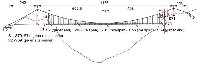
图1
悬索桥立面图及关键位置吊索示意图
Fig.1
Schematic diagram of side elevation of the suspension bridge and suspenders at key positions (Unit: m)
1.2 风-车流-桥耦合振动系统
本研究所采用的风-车流-桥耦合系统[19]是基于有限元法建立的仿真平台,该系统综合考虑了桥梁结构、随机风和车流之间的动态相互作用。整个仿真过程包含3个步骤:首先,建立桥梁和车辆的数值模型,在ANSYS中获得桥梁质量、刚度矩阵;其次,模拟随机风场和车流情况,计算作用在桥梁和车辆上的风荷载以及车桥相互作用力;最后,建立风-车流-桥耦合振动系统的控制方程如下式所示,并在MATLAB中进行风-车流-桥耦合动力学分析。
式中:n为车流中的车辆总数;q为位移矢量;M为结构质量矩阵;C为阻尼矩阵;K为刚度矩阵;F为力矩阵;下标b和νi (i=1,2,3...n) 分别表示桥梁系统和第i辆车;上标G、R、C、W、Se和Bu分别表示对应于重力、路面不平度激励、车桥耦合相互作用、静风、自激和抖振力的激励荷载。
通过求解风-车流-桥耦合控制方程,可以基于挠度-应变关系和应力-应变关系进一步计算得到应力矢量,如下式所示:
式中:[S]为应力矩阵;[E]为应力-应变关系矩阵;[B]是由单元形状函数推导出的应力-挠度关系矩阵。
1.3 吊索应力时程数据
风、车流荷载工况设置如下:风速共计4种,即10.5、13.5、16.5和20.0 m/s;桥上车流荷载考虑3种情况,即无车流、稀疏车流和拥堵车流工况。本研究中随机车流采用元胞自动机 (CA) 模型进行模拟,具体模拟方法及步骤详见文献[19],在此不再赘述。图2给出了风和车流荷载联合作用下S1 (地面吊索)、S19 (1/4跨吊索)、S36 (跨中吊索) 的应力时程。如图2所示,总体来讲,车流荷载主要对吊索应力响应的均值起控制作用,而风荷载主要对吊索应力响应脉动分量的改变占据主导地位。这是由于车流荷载的自重作用会导致主梁有一定的整体下挠 (相当于静载) ;同时,由于车流荷载的随机性,车流荷载也会有上下波动,这也会导致主梁在整体下挠的同时会有一定程度的上下振动。而风荷载与车流荷载不同,风荷载是一个脉动荷载,该脉动风荷载仅会导致吊索应力呈现脉动变化。因此,车流荷载主要影响吊索的应力响应均值,风荷载主要影响吊索应力响应的脉动部分。随着风速的增加,风荷载对吊索应力响应脉动成分的影响更显著。采用雨流计数法对图2中各吊索的应力时程进行统计,得到吊索在风和车流荷载联合作用下的等效应力幅值及对应的循环次数 (已换算为1 d),如表1所示[19]。
图2
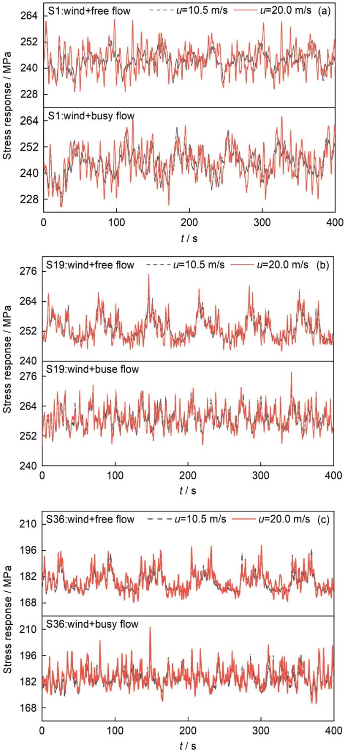
图2
风-车流联合作用下吊索S1、S19和S36的应力时程曲线
Fig.2
Stress response time histories of three typical suspenders S1 (a), S19 (b) and S36 (c) under combined load of wind and traffic flow
表1 一天之内吊索S1、S19、S36在不同风速、车流工况下应力数据统计[19]
Table 1
| Traffic flow | um/s | Equivalent stress range values / MPa | Numbers of stress cycles | ||||
|---|---|---|---|---|---|---|---|
| S1 | S19 | S36 | S1 | S19 | S36 | ||
| No flow | 10.5 | 7.71 | 4.06 | 4.19 | 10080 | 3312 | 5904 |
| 13.5 | 10.78 | 5.50 | 5.59 | 11952 | 8064 | 12240 | |
| 16.5 | 15.28 | 7.37 | 8.67 | 14256 | 10368 | 14544 | |
| 20.0 | 15.79 | 7.79 | 9.46 | 17424 | 117280 | 18144 | |
| Free flow | 10.5 | 12.25 | 13.65 | 14.91 | 8352 | 8928 | 10224 |
| 13.5 | 13.07 | 13.42 | 14.89 | 11952 | 11664 | 12528 | |
| 16.5 | 15.87 | 13.60 | 16.25 | 13824 | 13536 | 15408 | |
| 20.0 | 17.19 | 13.37 | 14.44 | 16992 | 19008 | 18288 | |
| Busy flow | 10.5 | 14.96 | 11.89 | 13.06 | 9936 | 14400 | 18288 |
| 13.5 | 15.76 | 11.85 | 13.73 | 11952 | 16848 | 19872 | |
| 16.5 | 17.33 | 12.84 | 14.95 | 13680 | 16704 | 19728 | |
| 20.0 | 18.39 | 12.86 | 15.68 | 17136 | 19440 | 21024 | |
2 双蚀坑钢丝损伤模型
连续介质损伤力学的基本思想是通过引入损伤变量这一宏观物理量,用于描述钢丝内部微观结构的失效过程。将损伤变量定义为D,表现为钢丝的有效截面的损伤,若损伤变量D为0,表示钢丝完好无损;D为1时,表示钢丝完全损坏,D的计算式如下式所示:
式中:A为钢丝初始横截面面积;
在外力F作用下,钢丝的有效应力
2.1 钢丝的弹塑性本构关系
钢丝表面出现蚀坑后,会导致在该区域引起应力集中现象,钢丝在外力作用下会出现塑性变形。双蚀坑钢丝引起的应力集中现象更为突出,因而采用弹塑性本构模型来描述蚀坑周围的实际应力状态。根据Lemaitre[17]提出的理论,将损伤变量D引入,钢丝本构模型如下式所示:
式中:E和v分别为Young模量和未损伤材料的Poisson比;
将单根钢丝视为单轴受拉构件,考虑损伤变量后的钢丝本构模型采用双线性随动强化模型 (BKIN) 拟合,如下式所示:
式中:
2.2 钢丝的弹塑性损伤演化模型
对
式中:
由于蚀坑钢丝在整个疲劳损伤过程中存在塑性变形,Cui提出了关于塑性疲劳损伤的模型如下式所示[16]:
式中:
2.3 双蚀坑钢丝有限元模型
图3
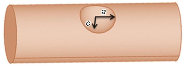
图3
含单个半椭球形状蚀坑的钢丝示意图
Fig.3
Schematic diagram of a steel wire with a single semi-ellipsoidal pit
采用ANSYS建立双蚀坑钢丝模型,蚀坑之间的距离用夹角
图4
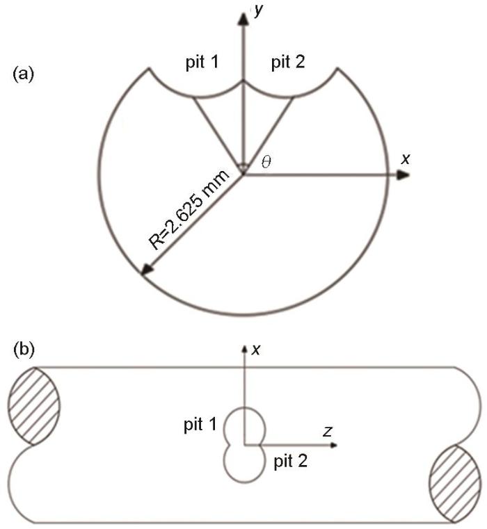
图4
含两个半椭球形状蚀坑的钢丝横截面图和俯视图
Fig.4
Sectional view (a) and top view (b) of the steel wire with double semi-ellipsoidal pits
双蚀坑钢丝有限元模型采用SOLID95单元,以直径为5.25 mm的圆柱模拟蚀坑钢丝,钢丝长度为20 mm,蚀坑位于钢丝中部。钢丝弹性模量为2.1×10⁵ MPa,泊松比为0.3,抗拉强度为1670 MPa,密度为7850 kg/m3。
对钢丝蚀坑附近的网格进行细化,验算4种不同网格尺寸,一般认为,当最大节点应力 (
表2
4种网格尺寸条件下
Table 2
| Mesh accuracy mm | Maximum nodal stress MPa | Maximum element stress MPa | |
|---|---|---|---|
| 0.1 | 808.79 | 812.52 | 99.54% |
| 0.2 | 800.63 | 810.75 | 98.75% |
| 0.3 | 789.99 | 814.45 | 97.00% |
| 0.4 | 764.50 | 841.50 | 90.85% |
综合考虑计算时间和计算精度,最终取钢丝蚀坑附近区域的网格尺寸为0.1 mm,其他区域网格尺寸为0.2 mm (图5)。
图5

图5
双蚀坑钢丝有限元模型网格划分
Fig.5
Mesh division of finite element model for the steel wire with double corrosion pits
3 双蚀坑钢丝损伤演化模拟
3.1 施加循环荷载及确定荷载循环区
对双蚀坑钢丝模型一端进行固定约束,另外一端施加如下式所示的循环荷载:
式中:
图6

3.2 吊索钢丝损伤演化模拟
图7

图7
不同时间点钢丝双蚀坑附近等效应力云图
Fig.7
Von Mises stress contours nearby the double corrosion pits after operation for 17.5 a (a), 25.0 a (b), 30.0 a (c) and 38.5 a (d)
在该工况条件下,双蚀坑钢丝的腐蚀疲劳寿命为38.5 a。而双蚀坑钢丝在17.5 a时出现第一个被杀死的单元 (即该单元的损伤变量达到1),图8为第一个被杀死单元的损伤变量曲线,钢丝的损伤变量在10 a以前变化缓慢,10 a后损伤变量快速增长并迅速达到阈值。从双蚀坑钢丝第一个被杀死的单元出现直至双蚀坑钢丝完全损伤历经21 a,占双蚀坑钢丝总腐蚀疲劳寿命的54.5%。
图8
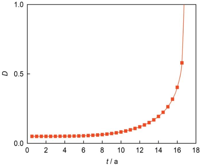
图9为在不同时间点时沿钢丝z轴和x轴方向上双蚀坑附近的等效应力分布曲线。沿z轴方向上的应力曲线大致呈抛物线形状,在钢丝蚀坑中心处应力值最大,随时间推移,裂纹沿着x方向不断扩展,直至钢丝完全失效。沿x轴的应力曲线呈现二级阶梯形状,这是由于钢丝蚀坑中心处和边缘位置都存在应力集中效应,但钢丝蚀坑中心处应力集中效应明显高于边缘位置的应力集中效应。
图9
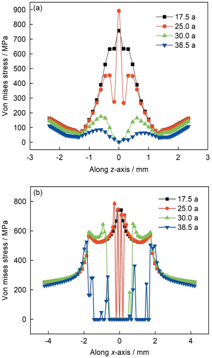
图9
沿钢丝z轴和x轴方向双蚀坑附近的等效应力分布
Fig.9
Von Mises stress distribution nearby the double corrosion pits along z-axis (a) and x-axis (b)
4 参数分析
本节主要探讨风速,车流,吊索位置,蚀坑形状参数,蚀坑形状不对称等因素对双蚀坑吊索钢丝腐蚀疲劳寿命的影响。
4.1 风速影响
图10

图10
不同风速下吊索钢丝的损伤变量曲线
Fig.10
Damage degrees of suspender steel wire at different wind speeds
4.2 车流量的影响
设定吊索钢丝的双蚀坑形状对称且蚀坑形状参数
图11
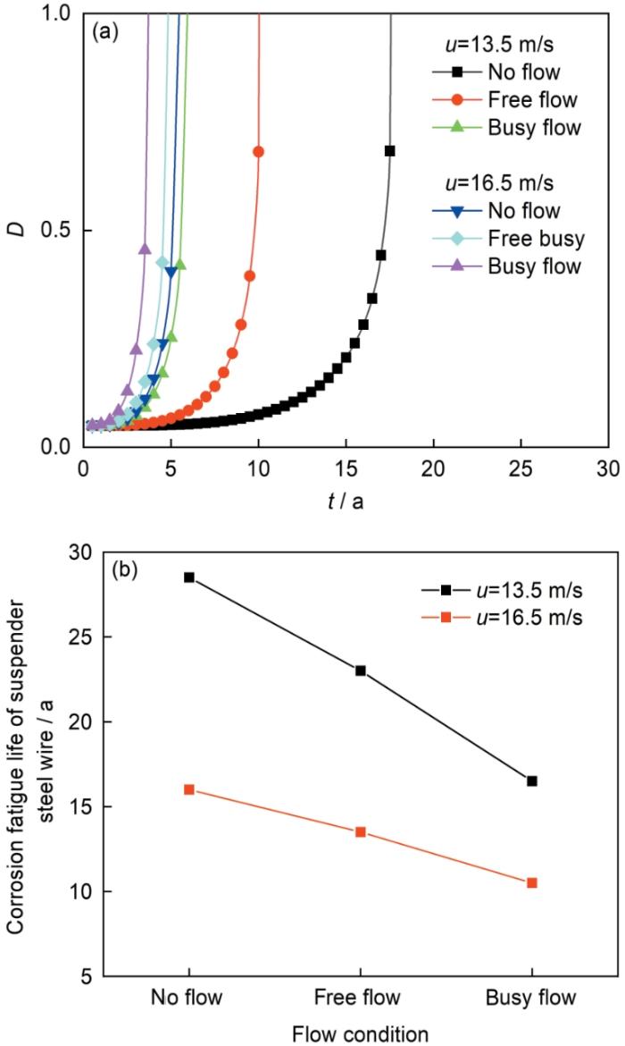
图11
不同车流下吊索钢丝的损伤变量曲线和腐蚀疲劳寿命曲线
Fig.11
Damage degrees (a) and corrosion fatigue life (b) of suspender steel wire under different traffic flow conditions
4.3 吊索位置的影响
为探究吊索位置对双蚀坑吊索钢丝腐蚀疲劳寿命的影响,在风速为10.5 m/s,稀疏车流情况下,双蚀坑形状对称且蚀坑形状参数
图12

图12
不同位置吊索钢丝的损伤变量曲线
Fig.12
Damage degrees of suspender steel wire at different positions
4.4 蚀坑形状参数的影响
设定双蚀坑形状对称,蚀坑间距
图13
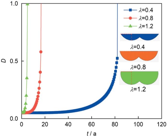
图13
不同形状参数下吊索钢丝的损伤变量曲线
Fig.13
Damage degrees of suspender steel wire under different shape parameters
4.5 蚀坑形状不对称的影响
为探究蚀坑形状不对称对吊索钢丝疲劳寿命的影响,本节设定蚀坑间距
图14

图14
蚀坑形状不对称下吊索钢丝的损伤变量曲线
Fig.14
Damage degrees of suspender steel wire with asymmetrical pits
5 结论
(1) 在双蚀坑钢丝的腐蚀疲劳损伤过程中,钢丝蚀坑中心处应力集中效应高于蚀坑边缘应力集中效应,钢丝蚀坑中心处最早出现裂纹,然后裂纹不断扩展,直至钢丝完全失效。
(2) 双蚀坑钢丝的腐蚀疲劳寿命对高风速更加敏感;同一风速下,车流量越大,对钢丝的腐蚀疲劳寿命越不利。
(3) 位于桥梁跨中的短吊索钢丝比地面长吊索钢丝和1/4跨吊索钢丝的腐蚀疲劳寿命更短。
(4) 蚀坑的深宽比越大,即形状参数越大,蚀坑越尖锐,在蚀坑底部会出现更高的应力集中效应,对钢丝的腐蚀疲劳寿命越不利;钢丝的蚀坑形状不对称时,吊索钢丝的腐蚀疲劳寿命主要由形状参数较大的蚀坑所决定。
参考文献
Analysis on damage evolution and corrosion fatigue performance of high-strength steel wire for bridge cable: experiments and numerical simulation
[J].
Fatigue reliability-based replacement strategy for bridge stay cables: a case study in China
[J].
Analysis on corrosion-fatigue damage and fracture mechanism of cables/hangers in service bridges
[J].
在役桥梁拉吊索腐蚀-疲劳损伤与破断机理分析
[J].
拉吊索(悬索桥的吊索、斜拉桥的斜拉索以及中、下承式拱桥的吊索)是拉索桥梁的重要承重构件,其服役可靠性直接影响这些桥梁的安全性。以拉吊索病害特性为导向,通过有限元分析、索体钢丝的腐蚀-疲劳模拟试验,结合理论分析研究拉吊索的损伤与破断机理,以期为拉吊索的设计、养护以及检测提供参考。首先通过有限元分析发现若下锚固区发生0.001 13 rad的转角,该处产生的弯曲应力就有18.8 MPa,研究下锚固区索体钢丝的病害不能忽视弯曲应力的影响,弯曲应力也是造成长拉吊索发生破断病害的因素之一;接着以近5 a中国西南地区雨水中形成酸雨的离子浓度的平均值为基准值,在盐雾腐蚀箱中模拟酸雨环境,将直径7 mm抗拉强度为1 860 MPa的镀锌钢丝在盐雾腐蚀箱中模拟酸雨腐蚀环境与交变应力耦合作用下索体钢丝的腐蚀-疲劳试验,研究其腐蚀-疲劳损伤机理。研究表明:服役的桥梁拉吊索在腐蚀环境和交变应力耦合作用下发生腐蚀-疲劳损伤,腐蚀-疲劳致使构件腐蚀加剧,塑性降低,脆性增强,发生脆性破断,若在设计、检测、评估分析中对结构的腐蚀-疲劳损伤考虑不充分就会有重大安全隐患;弯曲应力也是造成长拉吊索发生破断病害的因素之一;在相同的腐蚀环境下,随着时间的增加,交变应力工况试件的腐蚀程度最大,其次是静态应力工况,无应力工况下的腐蚀程度最小;试件发生腐蚀-疲劳损伤后,其破断应力约为无腐蚀试件的60%,断后伸长率降低得更多,约为无腐蚀试件的40%,断口表现为脆断;发生腐蚀-疲劳损伤的拉吊索钢丝,若有复杂空间应力的作用,更易发生脆断。
Corrosion fatigue crack growth prediction model based on stress ratio and threshold for marine engineering steel DH36Z35 in seawater
[J].
考虑应力比和门槛值的海水腐蚀疲劳裂纹扩展预测模型
[J].
Effect of industrial atmospheric environment on corrosion fatigue behavior of Al-Mg-Si alloy
[J].
工业大气环境对Al-Mg-Si合金腐蚀疲劳特性的影响
[J].使用力学性能测试、轴向力加载疲劳测试、扫描电子显微镜、电化学测试等手段,研究了模拟工业大气环境中Al-Mg-Si合金母材及其焊接接头的腐蚀疲劳特征。结果表明:Al-Mg-Si合金对接焊接接头的力学性能低于母材,而且在模拟工业大气环境中更易腐蚀。焊接接头的腐蚀疲劳敏感性更高,原因是其焊接缺陷处容易成为腐蚀疲劳裂纹优先萌生的区域,最终导致试样在焊缝区域发生疲劳断裂。
Model for prediction of fatigue lives based upon a pitting corrosion fatigue process
[M]//Fong J T.
Fatigue life evaluation of high-strength steel wires with multiple corrosion pits based on the TCD
[J].
Prediction of fatigue crack initiation life based on pit growth
[J].
Study on stress intensity factor of double pits in corroded cable wires
[J].
腐蚀拉索钢丝的双蚀坑应力强度因子研究
[J].
Research of the effect of erosion pits on the stress intensity factor of cable wire
[J].
斜拉索平行钢丝多蚀坑应力强度因子研究
[J].
The research on stress intensity factor and remaining life of cable wire with multiple corrosion holes
[D].
拉索钢丝多蚀坑应力强度因子及剩余寿命研究
[D].
The research on stress intensity factor and extended life for double pits of cable wire
[D].
拉索钢丝双蚀坑应力强度因子及其扩展寿命研究
[D].
A continuum damage mechanics model for high cycle fatigue
[J].
A continuum damage mechanics model for pit-to-crack transition in AA2024-T3
[J].
Corrosion-fatigue life prediction for 2024-T62 aluminum alloy using damage mechanics-based approach
[J].An approach based on the continuum damage mechanics was applied to predict corrosion–fatigue crack initiation life of 2024-T62 aluminum alloy. A fatigue test in air, a pre-corrosion–fatigue test, and a corrosion–fatigue test on smooth standard specimens were performed. The fatigue lives are strongly reduced by the corrosive environment of 5 wt.% NaCl continuous salt spray compared with non-corroded specimens. Damage evolution models for fatigue in air and pre-corrosion–fatigue of smooth specimens were established, which forms the basis for solving the corrosion–fatigue problem. Finally, the method of corrosion–fatigue life prediction was presented. The predictions comply with the experimental data.
An improved continuum damage mechanics model for evaluating corrosion-fatigue life of high-strength steel wires in the real service environment
[J].
A continuum model for damage evolution simulation of the high strength bridge wires due to corrosion fatigue
[J].
Fatigue assessment on suspenders under stochastic wind and traffic loads based on in-situ monitoring data
[J].As a critical component of a suspension bridge, the integrity of the suspenders plays a critical role in the serviceability and reliability of the bridge during its life time. Despite the wide recognition of the importance of the suspenders, very few studies have been devoted to the condition evaluation of suspenders in operation. The present study performs the fatigue assessment on the suspenders accounting for the stochastic wind and traffic loads using the in-situ monitoring data. To this end, a probabilistic numerical framework is proposed to predict the time-dependent fatigue reliability of the suspenders under stochastic wind and traffic loads during the bridge’s life time, based on the linear fatigue damage rule. As a demonstration, the proposed numerical framework is applied to a long-span suspension bridge located in a mountainous canyon. The results indicate that it is of paramount importance to consider both the wind and traffic load effects in the fatigue reliability evaluation of the suspenders. In addition, it was also found that among the suspenders under investigation, the short suspender at the bridge mid-span (S36) is more prone to the fatigue damage, while the long suspender at the end of the bridge girder (S2) is less prone to the fatigue damage. Finally, provided with a target reliability index of 3.0, the fatigue life of the suspenders S36 and S2, considering the life time wind and traffic load, is estimated as 53 years and 167 years, respectively. The present research could provide essential guidelines for the optimization of inspection and replacement in maintenance practices for suspenders.
A continuum damage mechanics approach coupled with an improved pit evolution model for the corrosion fatigue of aluminum alloy
[J].
A damage mechanics approach to fretting fatigue life prediction with consideration of elastic-plastic damage model and wear
[J].
Numerical investigation on stress concentration of corrosion pit
[J].
