


海洋工程逐渐从浅海 (<500 m) 走向深海 (500~1000 m) 甚至是超深海 (超过1500 m)[1,2],与大陆架浅海环境相比,深海、超深海存在着巨大的静水压力,而一些海洋特种设备如潜艇、深潜器等在水下作业时,将频繁经历交变压力的服役工作环境[3-6]。施加防护涂层是延缓、阻止金属腐蚀的重要方法之一[7,8]。现今对涂层在常压及深海中静水压力环境下的失效机理已经有着较为详细的研究[9-13]。Liu等[14]对一种Cr/GLC涂层进行了模拟深海环境中30 MPa静水压力对涂层腐蚀行为的影响研究,探究了多层结构涂层在模拟深海环境静水压力下的腐蚀机理;Tian等[15]对一种溶剂型的环氧层体系在模拟海洋交变压力下的破坏行为进行了研究,分析了在0.1~6 MPa交变压力下的涂层失效过程,结果表明海水交变压力使涂层/钢体系结构恶化,涂层失效速率加快。现今关于超深海环境下的交变压力对防腐涂层失效机理研究鲜有报道。
本文以深海海洋装备目前常用的环氧粉末重防腐涂料和无溶剂环氧液体重防腐涂料为研究对象,通过模拟超深海0.1~20和0.1~30 MPa交变压力的实验环境探究2种无溶剂环氧防腐涂层在交变压力作用下的电化学失效机理,采用电化学阻抗谱 (EIS)、LEIS等电化学手段和扫描电镜 (SEM) 等测试手段分析涂层失效过程。为服役于苛刻深海交变压力环境下的重防腐环氧涂料研发和应用提供实验依据和理论依据。
1 实验方法
实验采用海洋装备中常用的低合金钢Q345作为基材,其化学成分 (质量分数,%) 为:C 0.18,Mn 1.42,Si 0.41,P 0.015,S 0.016,Fe余量。将Q345钢加工成15 mm×15 mm×3 mm的样板,对其中一面进行喷砂处理达Sa2.5级,相对一面进行打磨抛光处理,然后先用丙酮除去表面油污,后用乙醇除去水份,再用超声清洗后吹干放置真空干燥箱中备用。本实验采用2种无溶剂环氧防腐涂料,分别为环氧粉末涂料A,无溶剂环氧液体涂料B。环氧粉末涂料A的配方各组分质量比为:改性固体环氧树脂54%~60%,改性酚类固化剂10%~12%,固化促进剂0.05%~0.2%,填料占比30%~36%;无溶剂环氧液体涂料B的配方各组分质量比为:为液体环氧树脂30%~40%,改性酚醛胺类固化剂25%~30%,填料占比30%~36%,两种涂层复配填料均为涂料级硫酸钡、云母、缓蚀型颜填料。
环氧粉末涂层A (涂层A) 制备:将表面锈迹处理好的Q345放入 (恒温加热炉中预热240±2) ℃×10 min,然后在Q345测试表面用静电粉末喷枪涂方法喷涂环氧粉末涂料A,再将其放入恒温加热炉中固化 (230±2) ℃×15 min,取出后在室温下冷却,通过差示扫描量热仪 (DSC) 检测,涂层固化完全后的玻璃化温度 (Tg) 约为145 ℃。无溶剂环氧液体涂层B (涂层B) 制备:采用自动涂膜器在50%湿度室温条件下制备样品,待其在室温实干后,置于 (80±2) ℃烘箱中充分固化12 h,取出后在室温下冷却,按照SY/T 0315检测,涂层固化完全后的Tg约为96 ℃。2种体系分别用TT10型磁性涂层测厚仪对样品进行厚度测试,挑选出涂层厚度为 (100±10) μm的试样作为实验样品。
电化学测试试样用环氧树脂灌封胶质量比A∶B=1∶2将涂层A、涂层B工作试样电极灌封于金相硅胶软模具中 (直径32 mm,高度20 mm),2.5 mm2铜导线焊接在Q345未喷涂的工作面相对面。为防止高压浸泡介质从边缘处渗透进涂层,在灌封时涂层只露出1 cm2的电极测试面积,其余部分全部用灌封胶包覆。
采用Cortest恒温恒压高压釜控制实验设计压力和温度模拟海水交变压力装置实验,实验介质为3.5% (质量分数) NaCl模拟海水溶液,模拟海水交变压力对比实验条件分别为:第Ⅰ组:常压0.1 MPa与高静水压力30 MPa循环加载,以24 h为一个周期,12 h变换一次压力,前12 h (半个周期) 为30 MPa浸泡,后12 h (半个周期) 为0.1 MPa浸泡,浸泡20个周期共480 h。第Ⅱ组:进行0.1~20 MPa交变压力实验,交变压力变换和时长与第Ⅰ组保持一致。实验温度均控制在室温 (25±1) ℃。
采用Reference 600电化学工作站,三电极体系进行电化学阻抗谱测试 (EIS),涂层/Q345试样为工作电极 (WE),铂电极 (20 mm×20 mm×0.5 mm) 为辅助电极 (CE),参比电极 (RE) 使用T30P5000-Re型高压参比电极 (美国CP PIPE&EQUIPMENT LLC),适用温度0~30 ℃,压力0.1~35 MPa,管体直径15 mm,其成分和常规Ag/AgCl参比电极成分一致。阻抗谱测试频率范围为105~10-2 Hz,由于涂层A,B体系较厚并且属于高阻值体系,浸泡初始正弦扰动信号设置为50 mV,后降至为20 mV。得到的数据用ZSimpWin软件进行拟合和分析处理。每组压力及每种涂层均采用3个平行样品。
经模拟海水0.1~20 MPa、0.1~30 MPa交变压力浸泡24、240及480 h的3个时间点的2种涂层样品采用Versa STAT 3F微区电化学工作站对同一位置的不同浸泡时间点的涂层局部腐蚀情况进行微区电化学阻抗谱 (LEIS) 测评,扫描范围为4000 μm×4000 μm,每个样品的同一位置做标记,以1 kHz的频率检测样品。将高压浸泡后的涂层样品在不同时间节点从高压釜中取出,并立即进行LEIS测试,测试结束后立刻放到高压釜中。
两种涂层体系经模拟海水0.1~30 MPa,0.1~20 MPa交变压力浸泡480 h后的样品采用FEI Quanta FEG 250场发射扫描电子显微镜 (FESEM) 对涂层下金属的腐蚀形貌进行观察,并用自带能量色散谱仪 (EDS) 对腐蚀产物元素成分进行分析。
2 结果与讨论
2.1 两种涂层体系在交变压力下的电化学阻抗测试
2.1.1 两种涂层体系在0.1~30 MPa交变压力下的EIS谱线
两种涂层体系在0.1~30 MPa交变压力下的EIS谱线 (图1) 为完整涂层A在0.1~30 MPa交变压力浸泡于3.5%NaCl腐蚀环境中480 h的EIS测试结果,表1为100 μm涂层A浸泡480 h的拟合数据结果。从图1a中可以看出,涂层A在浸泡了6 h后,Nyquist图表现为单一容抗弧响应,6 h的低频段阻抗值|Z|0.01 Hz为2.724×10¹⁰ Ω·cm2 (图1c),144 h后仍处于单容抗弧响应阶段,表明涂层A在浸泡了144 h后涂层的性能良好,在此时间点之前涂层的等效电路图如Model A (图1a) 所示,为涂层失效的第1阶段。从图1b中可以看出,在0.1~30 MPa交变压力作用下,240 h时涂层出现了明显的两个容抗弧响应,有2个时间常数,说明此时腐蚀介质已经渗透到涂层A/Q345钢界面,并开始与Q345钢界面发生电化学腐蚀反应,为涂层失效的第2阶段,涂层的等效电路图为Model B (图1b)。在240 h时 (图1c),涂层A的|Z|0.01 Hz下降到9.153×10⁹ Ω·cm2,此时的涂层仍然具有良好的保护性能[22],480 h时|Z|0.01 Hz为2.349×10⁸ Ω·cm2,480 h后涂层阻抗值分别下降了2个数量级,涂层阻隔性能下降明显,但仍具有一定的防腐性能。另外从图1d中Bode-Phase中频段时域 (10 Hz处) 可以看出在浸泡过程中,相位角和低频段阻抗模值的变化趋势整体具有一致性。
图1
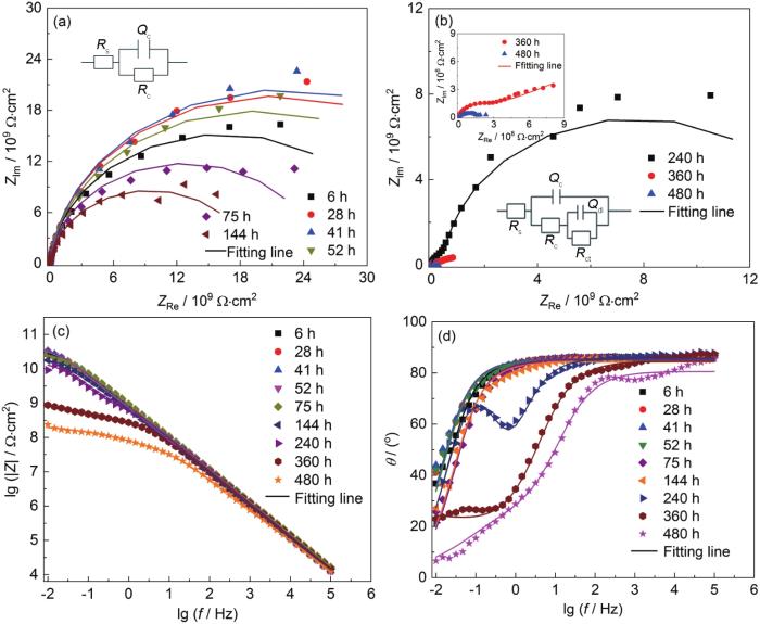
图1
涂层A在0.1~30 MPa交变压力下浸泡480 h后的EIS测试结果
Fig.1
Nyquist (a, b) and Bode (c, d) results of coating A after immersion for 480 h under 0.1-30 MPa alternating pressure
表1 涂层A在0.1~30 MPa交变压力下浸泡480 h期间EIS参数拟合结果
Table 1
| Time / h | Rc / Ω·cm2 | n1 | Qc / F·cm-2 | Rct / Ω·cm2 | n2 | Qdl / F·cm-2 | Zw |
|---|---|---|---|---|---|---|---|
| 6 | 3.287×10¹¹ | 0.9 | 2.291×10⁻¹⁰ | --- | --- | --- | --- |
| 28 | 4.258×10¹⁰ | 0.9492 | 2.324×10⁻¹⁰ | --- | --- | --- | --- |
| 41 | 4.43×10¹⁰ | 0.9477 | 2.37×10⁻¹⁰ | --- | --- | --- | --- |
| 52 | 3.909×10¹⁰ | 0.9441 | 2.486×10⁻¹⁰ | --- | --- | --- | --- |
| 75 | 2.556×10¹⁰ | 0.9 | 2.914×10⁻¹⁰ | --- | --- | --- | --- |
| 144 | 1.896×10¹⁰ | 0.9365 | 2.739×10⁻¹⁰ | --- | --- | --- | --- |
| 240 | 1.138×10⁹ | 0.954 | 2.943×10⁻¹⁰ | 1.386×10¹⁰ | 0.9676 | 3.81×10⁻¹⁰ | --- |
| 360 | 1.49×10⁸ | 0.3122 | 3.954×10⁻¹⁰ | 3.07×10⁹ | 0.3122 | 3.125×10⁻⁹ | --- |
| 480 | 4.447×10⁷ | 0.8951 | 5.105×10⁻¹⁰ | 1.835×10⁸ | 0.4922 | 6.488×10⁻⁹ | --- |
涂层B在0.1~30 MPa交变压力下浸泡于3.5% NaCl中480 h的EIS测试结果如图2所示,表2为100 μm涂层B浸泡480 h的拟合数据结果。浸泡6 h后,Nyquist图表现为单容抗弧响应 (图2a),涂层|Z|0.01 Hz为1.995×10¹⁰ Ω·cm2,28 h之前为涂层失效第1阶段,涂层的等效电路图为Model A (图2a);41 h时出现了第2个容抗弧,并且随着浸泡时间的延长,在75 h时已经出现了非常明显的第2容抗弧响应 (图2b),此时的|Z|0.01 Hz下降到1.479×10⁹ Ω·cm2 (图2d),此阶段的拟合电路为Model B (图2b);但在41~75 h的时间段内,|Z|0.01 Hz出现上升情况,原因可能是涂层B/Q345钢界面处发生了腐蚀反应,腐蚀产物堆积阻碍了侵蚀离子的渗透通道,在一定程度上延缓了Q345钢腐蚀反应的进行[23],为涂层失效第2阶段。浸泡240 h后,由Nyquist图 (图2c) 中可以看出,谱线出现了Warburg扩散反应,引入ZW进行拟合电路的表征[24,25],涂层的拟合电路图为Model C (图2c),为涂层失效的第三阶段;在浸泡480 h后,|Z|0.01 Hz下降到1.41×10⁷ Ω·cm2,480 h后涂层阻抗值分别下降了3个数量级,说明此时的涂层对基体的保护作用已经下降非常显著,对Q345基材失去了防护性能[26]。另外从图2e Bode-Phase中频段时域 (10 Hz处) 可看出,在浸泡过程中,相位角的变化趋势和|Z|0.01 Hz的变化趋势整体同样具有一致性,在浸泡480 h为10°,进一步说明了Q345基体界面出现较大程度的电化学腐蚀现象,在480 h后涂层B对Q345基体已经失去防腐效果。从0.1~30 MPa交变压力下480 h测试时间内,涂层A明显比涂层B耐蚀性好。
图2
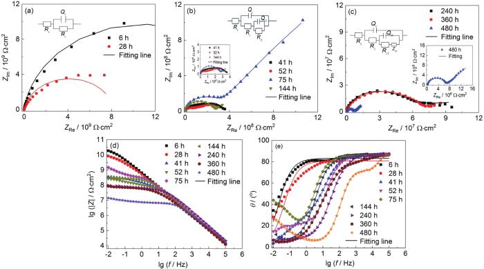
图2
涂层B在0.1~30 MPa交变压力下浸泡480 h后的EIS测试结果
Fig.2
Nyquist (a-c) and Bode (d, e) results of coating B after immersion for 480 h under 0.1-30 MPa alternating pressure
表2 涂层B在0.1~30 MPa交变压力下浸泡480 h期间EIS参数拟合结果
Table 2
| Time / h | Rc / Ω·cm2 | n1 | Qc / F·cm-2 | Rct / Ω·cm2 | n2 | Qdl / F·cm-2 | Zw |
|---|---|---|---|---|---|---|---|
| 6 | 2.186×10¹⁰ | 0.9246 | 2.797×10⁻¹⁰ | --- | --- | --- | --- |
| 28 | 8.24×10⁹ | 0.8976 | 3.682×10⁻¹⁰ | --- | --- | --- | --- |
| 41 | 6.425×10⁷ | 0.9578 | 4.089×10⁻¹⁰ | 3.303×10⁸ | 0.512 | 2.626×10⁻⁹ | --- |
| 52 | 5.344×10⁷ | 0.9584 | 8.099×10⁻¹⁰ | 4.179×10⁸ | 0.409 | 7.318×10⁻⁹ | --- |
| 75 | 3.188×10⁸ | 0.9524 | 9.204×10⁻¹⁰ | 1.217×10¹⁰ | 0.6368 | 4.376×10⁻⁹ | --- |
| 144 | 1.627×10⁸ | 0.9487 | 9.298×10⁻⁹ | 3.741×10⁸ | 0.6103 | 3.621×10⁻⁹ | --- |
| 240 | 4.078×10⁵ | 0.9671 | 1.134×10⁻⁸ | 8.643×10⁶ | 0.8 | 1.303×10⁻⁸ | --- |
| 360 | 8.964×10⁵ | 0.9535 | 1.136×10⁻⁸ | 7.24×10⁷ | 0.5437 | 1.472×10⁻⁹ | 3.332×10⁻⁷ |
| 480 | 1.615×10⁵ | 1 | 1.134×10⁻⁸ | 6.376×10⁶ | 0.8238 | 4.344×10⁻⁹ | 4.105×10⁻⁷ |
2.1.2 两种涂层体系在0.1~20 MPa交变压力下的EIS谱线
图3
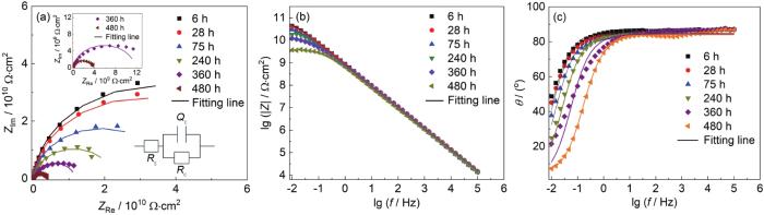
图3
涂层A在0.1~20 MPa交变压力下浸泡480 h后的EIS测试结果
Fig.3
Nyquist (a) and Bode (b, c) results of coating A after immersion for 480 h under 0.1-20 MPa alternating pressure
图4
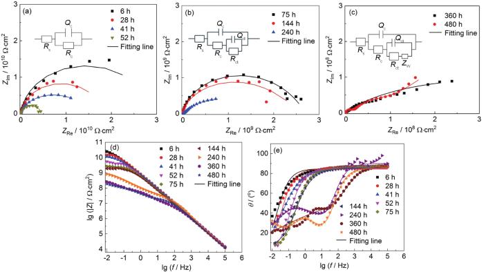
图4
涂层B在0.1~20 MPa交变压力下浸泡480 h后的EIS测试结果
Fig.4
Nyquist (a-c) and Bode (d, e) results of coating B after immersion for 480 h under 0.1-20 MPa alternating pressure
从图3a可以看出,涂层A在480 h浸泡过程中,仅仅表现为单容抗弧响应,对应的等效电路即拟合电路图为Model A (图3a),0.1~20 MPa交变压力浸泡480 h时间段内涂层A处于失效的第1阶段。|Z|0.01 Hz从浸泡6 h后的4.425×10¹⁰ Ω·cm2下降到480 h后的5.71×10⁹ Ω·cm2 (图3b);并且从图3c相位角中频段 (10 Hz) 可以看出相位角整体都在80°左右,同样说明在0.1~20 MPa交变压力下浸泡480 h后,涂层A仍然具有良好的保护性能,阻抗值整体下降不明显,与涂层A在0.1~30 MPa交变压力下浸泡480 h时|Z|0.01 Hz为2.349×10⁸ Ω·cm2相比,数据高了1个数量级;说明在浸泡过程中交变压力越大,腐蚀介质渗透到涂层中的速度越快,涂层的保护能力下降速率越快。
涂层B在0.1~20 MPa交变压力下浸泡52 h前 (图4a),测试结果表现出单容抗弧响应;在75~240 h时间内EIS测试结果虽无明显双容抗弧响应,但是使用拟合电路Model B能够得到良好的拟合效果,其原因是浸泡时间不足,腐蚀作用不明显 (图4b)。由图4c中可以看出,随着浸泡时间的延长,涂层表现出明显的双容抗弧响应,并且EIS谱线低频区域发生Warburg扩散现象,引入Zw (Model C) 进行拟合电路的分析。从图4e中频段 (10 Hz) 分析得出,涂层在浸泡480 h时中频相位角接近30°,表明涂层的防护性能下降明显。另外涂层B在0.1~20 MPa交变压力下|Z|0.01 Hz在浸泡初期到浸泡480 h后下降了约2个数量级,对比涂层B在0.1~30 MPa浸泡480 h后|Z|0.01 Hz下降了约3个数量级。进一步说明了越高的交变压力对涂层的防护能力下降越快,涂层更容易失去对金属的防腐性能。
2.1.3 电化学参数分析结果
图5
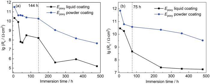
图5
涂层A和涂层B在交变压力下浸泡480 h后涂层电阻 (Rc) 的变化曲线
Fig.5
Variation curves of Rc after immersion of coating A and coating B under 0.1-30 MPa (a) and 0.1-20 MPa (b) alternating pressures for 480 h
在41~144 h时间段内,涂层A的Rc下降缓慢,而涂层B的Rc出现先上升后下降的过程,这与涂层B在0.1~30 MPa下的低频阻抗值|Z|0.01 Hz在同一时间段的规律一致。后在144~480 h时间段,涂层电阻持续下降,并且480 h后涂层B的Rc (1.615×10⁵ Ω·cm2) 较涂层A (4.447×10⁷ Ω·cm2) 下降的更加明显。分析原因可能是随着Q345钢表面腐蚀产物的生成和涂层B断面孔隙率的生成,涂层逐渐失去了对基体的保护作用。另外从0.1~20 MPa交变压力下的Rc变化来看 (图5b),涂层B的Rc在52 h之前缓慢下降,52~240 h时间段下降明显,而后又趋于平稳。说明在较低的交变压力作用下,涂层电阻Rc变化越小,电解质溶液渗透到涂层的速率越慢。
图6
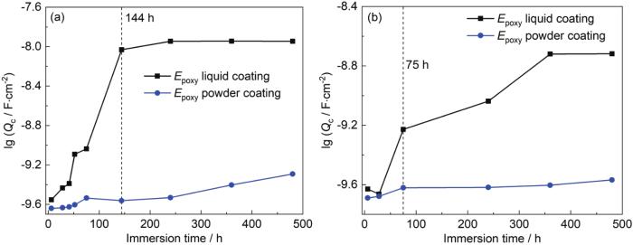
图6
涂层A和涂层B在交变压力下浸泡480 h后涂层电容 (Qc) 的变化曲线
Fig.6
Variation curves of Qc after immersion of coating A and coating B under 0.1-30 MPa (a) and 0.1-20 MPa (b) alternating pressures for 480 h
涂层B在0.1~30 MPa交变压力浸泡过程中,涂层电容Qc在144 h时间段内表现为快速上升趋势,144 h后出现平稳上升的现象 (图6a)。涂层B在0.1~20 MPa交变压力浸泡过程中的Qc在360 h之前都有较为快速的上升趋势,在480 h时有平稳趋势,总体上升范围从6 h的2.348×10⁻¹⁰ F·cm-2上升到480 h的1.912×10⁻⁹ F·cm-2,0.1~20 MPa交变压力整体变化范围小于在0.1~30 MPa交变压力的作用。这种现象的原因是由于较大交变压力环境促进腐蚀介质的渗透,导致涂层失效速率加快。
Qdl是界面双电层电容,代表涂层下Q345金属基材的腐蚀活性点的大小,Rct表示电荷转移电阻,是衡量涂层下的Q345钢腐蚀的难易程度,也能一定程度上表明涂层在模拟海水苛刻环境下的失效难易程度。从表1和2中可以看出,100 μm厚度涂层B在240 h时才开始出现Rct数据,为1010 Ω·cm2,480 h后下降了1个数量级;而涂层B在41 h就开始出现Rct,并且在浸泡整个过程中整体表现为下降趋势,480 h后下降了2个数量级;Qdl在2种涂层中的变化趋势与Rct大致相同。
2.2 两种涂层在不同交变压力下的LEIS测试
为探究完整涂层的局部腐蚀情况,本次实验采取在较高不同交变压力浸泡到一定时间后,不进行人工制造缺陷的步骤,直接采用LEIS进行涂层标记位置处的局部测试,以此来进一步探究在交变压力下作用下涂层的微观失效机理。实验测试时间点24、240和480 h均为同一位置不同时间点的测试结果。
图7
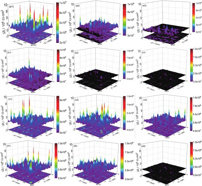
图7
两种涂层在交变压力作用下浸泡480 h后的LEIS结果图
Fig.7
LEIS results of the coatings A (a, c) and B (b, d) after immersion under 0.1-30 MPa (a, b) and 0.1-20 MPa (c, d) alternating pressure for 480 h
表3 两种涂层在不同交变压力浸泡480 h后的LEIS数据对比
Table 3
| Alternatingpressure | |Z|1 kHz | Coating A | Coating B |
|---|---|---|---|
| 0.1-30 MPa | Max | 3×10⁸ Ω·cm2 | 6×10⁷ Ω·cm2 |
| Min | 2×10⁶ Ω·cm2 | 4×10⁵ Ω·cm2 | |
| 0.1-20 MPa | Max | 6×10⁸ Ω·cm2 | 1×10⁸ Ω·cm2 |
| Min | 2×10⁷ Ω·cm2 | 2×10⁶ Ω·cm2 |
涂层A在0.1~20 MPa交变压力作用下的LEIS图像中阻抗云图并未出现黑色 (图7c),并且在整体过程中出现最高的阻抗值和最小的腐蚀面积,480 h的阻抗值最大为6×10⁸ Ω·cm2,最小为2×10⁷ Ω·cm2,这是因为涂层A在较低的交变压力0.1~20 MPa作用下,腐蚀介质扩散速率慢,基体界面腐蚀程度微小。这一现象与宏观EIS数据相对应。
2.3 涂层/Q345钢界面的形貌观察和腐蚀产物分析
2种涂层试样经过模拟超深海0.1~30和0.1~20 MPa交变压力环境下浸泡480 h后,采用SEM观察基体界面形貌,并用自带EDS分析了涂层下腐蚀产物的成分及含量 (表4)。
表4 涂层A和涂层B分别在不同交变压力下浸泡480 h后的Q345基体表面元素分析
Table 4
| Element | Coating A | Coating B | |||
|---|---|---|---|---|---|
| 0.1-30 MPa | 0.1-20 MPa | 0.1-30 MPa | 0.1-20 MPa | ||
| Fe | 90.32 | 93.15 | 52.53 | 76.71 | |
| O | 3.35 | 1.87 | 36.31 | 16.89 | |
| Cl | 0.68 | 0.10 | 4.75 | 0.98 | |
| Na | 1.54 | 0.15 | 1.63 | 0.50 | |
| C | 4.11 | 4.73 | 4.78 | 4.92 | |
图8

图8
两种涂层在交变压力浸泡480 h后的表面SEM像
Fig.8
Surface SEM images of the coatings A (a, c) and B (b, d) after immersion under 0.1-30 MPa (a, b) and 0.1-20 MPa (c, d) alternating pressure for 480 h
从相同测试模拟环境下的图8a和c来看,涂层A表现为优异的耐腐蚀性,并且只表现出极轻微的腐蚀程度。可得出涂层A在浸泡过程中会明显延缓腐蚀介质的渗透,给予Q345基体优异的耐腐蚀性能;并且也可以看出越低的交变压力作用下,涂层耐腐蚀性能越好。
从浸泡后的腐蚀产物分布及基体表面的元素分析可知,在相同的交变压力作用下,涂层A的电化学防腐性能优于涂层B,分析原因是由于两种无溶剂环氧涂层涂料材料组成、涂层成膜工艺上的差异,涂层A环氧粉末涂料通过粉末静电喷涂熔融结合成膜工艺,固化温度较高,涂层的玻璃化温度和致密性较高,粉末熔融交联固化后与Q345钢形成共价键为主的化学键,其粘结强度较涂层B以范德华力、氢键粘结机制有着本质的差别,并且改性环氧树脂与酚醛类固化剂固化形成的涂层A内部的高分子交联致密度较高,达到较高的玻璃化温度,从而在多方面保证了涂层A与Q345钢的附着力和介质的抗渗透性,从根本上提高了涂层A的在模拟超深海交变压力作用下的防腐性能。
3 结论
(1) 环氧粉末涂层A较无溶剂环氧涂层B在模拟超深海交变压力作用下对涂层的耐腐蚀性表现更加优异,在0.1~30 MPa、0.1~20 MPa模拟海水交变压力环境中能够更好的保护Q345等钢基材不被腐蚀。
(2) 较高的交变压力作用下,电解质溶液进入涂层内部的速率加快,更大程度上减弱涂层与Q345基体之间的粘结强度,加速了Q345基体的腐蚀速率。
(3) 环氧粉末涂层A因在成膜工艺、材料组成方面与无溶剂环氧涂层B的不同,延长了环氧粉末涂层A在模拟海水交变压力作用下的服役寿命。
参考文献
Influences of deep sea environmental factors on corrosion behavior of carbon steel
[J].
深海环境因素对碳钢腐蚀行为的影响
[J].
Research on the protective behavior of high solid content epoxy anti-corrosive coating/aluminum alloy system in simulated ultra-deep sea high-pressure environment
[J].
高固体分环氧防腐蚀涂层/铝合金在模拟超深海高压环境下的防护行为研究
[J].
Influence of simulated deep sea pressured-flowing seawater on failure behavior of epoxy glass flake coating
[J].
深海压力-流速耦合环境对环氧玻璃鳞片涂层失效行为的影响
[J].
Research progress of stress corrosion cracking of Ti-alloy in deep sea environments
[J].
钛合金深海应力腐蚀研究进展
[J].
Superior corrosion resistance and self-healable epoxy coating pigmented with silanzied trianiline-intercalated graphene
[J].
A review of studies on corrosion of metals and alloys in deep-sea environment
[J].
Performance of two new epoxy resins as potential corrosion inhibitors for carbon steel in 1 M HCl medium: combining experimental and computational approaches
[J].
Corrosion of epoxy-coated reinforcement in marine bridges with locally deficient concrete
[D].
Hydrostatic pressure effects on corrosion behavior of X70 pipeline steel in a simulated deep-sea environment
[J].
Effect of hydrostatic pressure on the corrosion behavior of HVOF-sprayed Fe-based amorphous coating
[J].
Performance of curing epoxy resin as potential anticorrosive coating for carbon steel in 3.5%NaCl medium: Combining experimental and computational approaches
[J].
Galvanic corrosion behavior of low alloy steel, stainless steel and Al-Mg alloy in simulated deep sea environment
[J].
低合金钢、不锈钢和铝镁合金在模拟深海环境中的电偶腐蚀行为研究
[J].
Effect of hydrostatic pressure on corrosion behavior of X70 steel in simulated sea water
[J].
静水压力对X70钢在海洋环境中腐蚀行为影响研究
[J].
Cr/GLC multilayered coating in simulated deep-sea environment: corrosion behavior and growth defect evolution
[J].
The failure behaviour of a commercial highly pigmented epoxy coating under marine alternating hydrostatic pressure
[J].
Failure behavior of solvent-free epoxy coating in simulated flowing sea water
[J].
模拟流动海水条件下无溶剂环氧防腐涂层的失效行为
[J].
Electrochemical behavior of solvent-free epoxy coating during erosion in simulated flowing sea water
[J].
无溶剂环氧防腐涂层在模拟海水冲刷条件下的电化学行为
[J].
Degradation behavior of solvent-free epoxy coatings in simulated flowing sea water with sand by different flow rates
[J].
无溶剂环氧防腐涂层在不同流速模拟海水冲刷条件下的失效行为
[J].
Active anti-corrosion of epoxy coating by nitrite ions intercalated MgAl LDH
[J].
Incorporation of electroconductive carbon fibers to achieve enhanced anti-corrosion performance of zinc rich coatings
[J].
Silk fibroin-Ti3C2TX hybrid nanofiller enhance corrosion protection for waterborne epoxy coatings under deep sea environment
[J].
Influence of fusion bonded epoxy powder on corrosion, wear performance of galvanized composite coating and hydrogen permeation behavior to based carbon steel
[J].
Failure behaviour of an epoxy coating with polyaniline modified graphene oxide under marine alternating hydrostatic pressure
[J].
Fluorinated graphene film for corrosion control on copper: experimental and theoretical studies
[J].
Tuning F-doped degree of rGO: restraining corrosion-promotion activity of EP/rGO nanocomposite coating
[J].
Given that graphene features high electrical conductivity, it is a kind of material with corrosion-promotion activity. This study aimed to inhibit the corrosion-promotion activity of graphene in coatings. Here, we report an exciting application of epoxy matrix (EP)/F-doped reduced graphene oxide (rGO) coatings for the long-term corrosion protection of steel. The synthesized F-doped rGO (FG) did not reduce the utilization of rGO by a wide margin and possessed distinctive electrically insulating nature. The electrical conductivity of rGO was approximately 1500 S/m, whereas those of FG-1, FG-2 and FG-3 were 1.17, 5.217 × 10⁻² and 3.643 × 10⁻¹¹ S/m, respectively. FG and rGO were then dispersed into epoxy coatings. The chemical structures of rGO and FG were investigated by transmission electron microscopy (TEM), scanning probe microscopy (SPM), X-ray photoelectron spectroscopy (XPS), Fourier-transform infrared spectroscopy (FT-IR), and X-ray diffraction (XRD). EP/FG coatings exhibited outstanding corrosion protection in comparison with blank EP and EP/rGO coatings mainly because the corrosion-promotion effect of rGO was eliminated. The anticorrosion ability of EP/FG coatings was improved with increased F-doped degree of FG. In addition, electrochemical impendance spectroscopy (EIS) results indicated that the Rc values of EP/FG-2 and EP/FG-3 were four orders of magnitude higher than those of EP/rGO in diluent NaCl solution (3.5 wt.%) after immersion for 90 days.
An SKP and EIS study of microporous nickel-chromium coatings in copper containing electrolytes
[J].The corrosion behaviour of microporous nickel-chromium systems was studied by means of conventional electrochemical techniques and localized ones using two chloride based electrolytes with and without cupric ions in their composition. The conscious combination of different methodologies using these techniques has provided valuable information about the corrosion process. Open Circuit Potential (OCP) and Electrochemical Impedance Spectroscopy (EIS) measurements were performed in bulk solution, whilst Scanning Kelvin Probe (SKP) measurement were carried out using two methodologies: i) electrolyte droplets monitoring (measuring simultaneously potential and droplet height with time), and ii) potential maps of dried surfaces that previously were exposed to droplets. Further characterization was done based on the morphology of the attack and composition on the surface by Optical Microscopy (OM), Field Emission-Scanning Electron Microscope (FE-SEM) and X-ray Photoelectron Spectroscopy (XPS) together with the analysis of electrolyte composition with time by Inductively Coupled Plasma-Optical Emission Spectrometry (ICP-OES). Results have shown the harmful effect of Cu2+ cations in the corrosion resistance and a different morphological impact on the surface. Such negative effect has revealed a new time constant at high frequency in the impedance diagrams as well as an abrupt potential decrease (due to a change in the cathodic reaction involved: Cu2+ + e(-) Cu+ takes place) using SKP droplet test. Apparently, Cu+ species were stabilized in bulk solution by the formation of chloride complexes, as was confirmed by the precipitation of a white CuCl compound during droplet evaporation, pointing out the key role of Cu thorn in the corrosion process. (C) 2019 Elsevier Ltd.
Electrochemical Impedance Spectroscopy (EIS): principles, construction, and biosensing applications
[J].
Corrosion resistance of graphene-reinforced waterborne epoxy coatings
[J].
