


蒸汽锅炉整体采用20#钢,蒸汽管路采用316L不锈钢,安全端给水管路采用两种钢焊接[4~6]。不锈钢具有更好的力学性能及耐腐蚀性能,因此在管路系统中大量使用不锈钢材料,从而在锅炉系统与管路系统之间引入异种金属焊接。在现场调查中,安全端给水管路的腐蚀所造成的泄漏往往会导致整体设备故障。异种金属焊接(DMW)会导致焊缝熔合线处的显微组织、化学成分和力学性能发生急剧变化。Yamazaki等[7]已使用单调蠕变实验研究DMW的不同失效模式,将不同区域的失效断裂情况及原因逐一分析[8~10]。其中,异种金属焊接试样热影响区的失效行为在文献[11,12]中被大量报道。碳钢与不锈钢异种金属焊接失效的原因可能是:(1) 由于C溶解度的巨大差异,C从热影响区(HAZ)扩散到奥氏体焊缝;(2) 热膨胀系数的差异;(3) 抗氧化性的差异。根据报道,热膨胀差异也会导致过热器管道中的DMW故障。焊接管路腐蚀失效通常是由液膜覆盖焊接接头后各种材料之间的电位差引起的。一般情况下,两种金属之间的在电位差(∆E)大于50 mV时发生电偶腐蚀,在∆E > 250 mV时变得极为严重[13~19]。
本文系统地研究了异种金属焊接管路在复杂耦合环境下发生电偶腐蚀,并与同种金属焊接管路进行对比,以阐明管路系统安全端腐蚀失效的原因。通过金相观察、电化学测试、浸没测试、四点弯曲测试对焊接接头的腐蚀失效进行了研究。
1 实验方法
1.1 样品制备
实验采用氩弧焊,焊接电流为80 A,电弧电压11 V,焊接速度6~8 cm/min,制作20#钢/碳钢焊材/20#钢焊接管线钢,以及20#钢/316L焊材/316L钢焊接管线钢,并用线切割方式分别取10 mm × 10 mm × 3 mm,50 mm × 10 mm × 2 mm,以及33 mm × 10 mm × 1.5 mm样品,并利用砂纸将其打磨至2000#。
1.2 模拟溶液
使用模拟供水管道的接触溶液作为实验溶液,正常水质与实际运行条件相对应。此外,为了有效地评估腐蚀行为,使用分析化学品、试剂化学品和去离子水(电阻率为18 MΩ/cm)设计了极端偏差水溶液。正常测试水样条件为:105 ℃-3 MPa,0.1 mg/L NaH2PO4-0.5 mg/L NaSO3,极端测试水样条件为:180 ℃-3 MPa,30 mg/L NaH2PO4-150 mg/L NaSO3。
1.3 腐蚀浸泡实验设置
图1
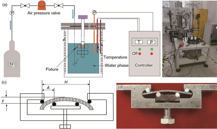
图1
腐蚀试验的示意图和实验设备
Fig.1
Illustrations and experimental setups for the corrosion test: (a) schematic diagram of the static immersion reactor, (b) physical photograph of the corresponding reactor, (c) schematic of the four-point bending (FPB) test configuration, (d) photograph of the actual four-point bending test fixture
1.4 失重测试
通过失重测试获得腐蚀速率,使用高精度电子天平(AH-A603H)称量已制备完成钢样的初始质量,再于240、480和720 h分别取出浸泡于模拟海水中的钢样,然后参照去除表面腐蚀产物方法除锈,充分干燥并称量除锈后的样品质量。腐蚀速率(Vcorr,mm/a)根据GB/T 39534-2020计算,计算公式如下:
其中,W0为试样腐蚀前的质量(g),W1为试样腐蚀后的质量(g),t为浸泡时间(h),ρ为不锈钢的密度(g/cm3),S为试样的总面积(cm2)。
1.5 样品表面、截面的宏观、微观形貌表征
浸泡测试结束后,使用去离子水冲洗试样表面,待其自然风干后,使用相机对试样进行宏观形貌拍摄。相机参数为:1200万像素广角镜头,放大倍数为3倍。先在试样表面喷金,以达到增强导电性的目的,然后使用PHILIPS XL-30FG型号扫描电镜(SEM)进行微观形貌表征,扫描电镜参数为:电压10 kV。对于截面样品,将其放入在模具中用封样剂固定,待封样剂固化后将试样表面依次用120#、400#、800#砂纸逐级打磨。截面形貌采用背散射模式,样品台高度设置为10 mm。为了表征裂纹扩展方式,先采用体积分数为4%的硝酸酒精溶液对20#钢区域进行刻蚀,再采用王水对20#/316L钢焊缝、316L不锈钢侧热影响区以及316L母材进行刻蚀。刻蚀后使用AxioObserverZ1M金相显微镜观察显微组织结构。
1.6 样品表面腐蚀产物的成分分析
采用Fourier变换红外光谱仪(FT-IR,Nicolet iS5)测试两种焊接接头浸泡试验后表面腐蚀产物成分,称取一定量的不同区域的腐蚀产物层样品,并向其中加入适量的KBr粉末,充分研细并混合均匀后,利用模具加压至5~10 t/cm2,制成透明的样品压片,最终置于光谱仪样品室中测试。测量光谱区域波数为400~4000 cm-1,设定扫描次数为20次。采用Raman光谱仪(XploRA PLUS)对两种焊接接头浸泡实验后表面腐蚀产物的成分进行分析,称取一定量的不同区域的腐蚀产物层样品,分析时激发波长为532 nm,扫描区间为100~1500 cm-1。
1.7 四点弯曲参数设置
对于焊接接头金属而言,应力腐蚀断裂诱导时间可能会持续数月乃至数年时间,导致应力腐蚀断裂的短时间复现相对困难,因此提出预制缺口的方法。为了尽快实现应力腐蚀,需要消除前期点蚀孕育时间,因此采用线切割方式在焊接接头靠近20#钢一侧切割0.5 mm的预制缺口。根据GB/T 15970.6-1998进行四点弯曲实验,实验参数见表1,夹具及样品装配实物图如图1c和d所示。对管段焊接接头样件,采用X射线衍射法(XRD,DS-21L大功率X射线应力仪),测量得到样件材料的晶面间距,判断出样件材料的宏观应变后,再根据Fuck定律通过计算可得到样件焊接残余应力的大小,计算方法及要求参照GB/T 7704-2017,得到20#钢/316L焊材/316L钢外表面和内表面的残余应力如图2。
表1 四点弯曲实验参数
Table 1
| Sample | Test number | Sample thickness / mm | Applied stress / MPa | Deflection / mm |
|---|---|---|---|---|
| 20#/20# steel | 1-1 | 1.40 | 240 | 0.172 |
| 1-2 | 1.37 | 240 | 0.176 | |
| 1-3 | 1.40 | 240 | 0.172 | |
| 20#/316L steel | 2-1 | 1.37 | 240 | 0.176 |
| 2-2 | 1.38 | 240 | 0.175 | |
| 2-3 | 1.39 | 240 | 0.173 |
图2
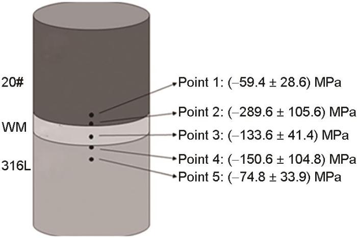
图2
20#钢/316L焊材(WM)/316L钢外表面和内表面的残余应力
Fig.2
Residual stress on the external and internal surfaces of 20# steel/316L welding material (WM)/316L steel
试样加载挠度通过
其中,σ为加载应力,E为弹性模量,t为试样厚度,y为最大挠度,H为外支点之间的距离,A为内外支点间距。
2 结果与讨论
2.1 显微组织
图3
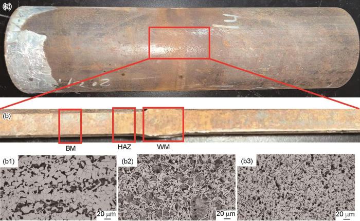
图3
20#/20#钢焊接接头的表面和截面宏观形貌及焊接头的显微组织
Fig.3
Surface (a) and cross-sectional (b) macro morphologies of 20#/20# steel welded joint, and microstructure morphologies of BM (b1), HAZ(b2) and WM (b3)
从图3b2可以看出,HAZ的显微组织主要由铁素体、珠光体组成。块状或条状的铁素体基体内分布着M-A岛状组织,M-A岛属于富碳相。与母材相比,热影响区晶粒尺寸粗大。
从图3b3可以看出,20#钢焊接头焊缝区(WM)组织主要由白色的铁素体(F)和黑色的珠光体(P)组成,在焊接过程中,焊缝处的温度会非常高,导致合金中的析出相会发生变化。焊接结束时冷却速度过快会使得原本较大的铁素体晶粒略微变小。焊接时采用的碳钢焊材,导致焊缝区含碳量增加,导致珠光体的数量略有增加。
图4
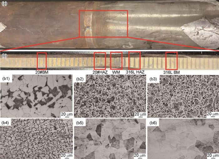
图4
20#/316L钢表面与截面宏观形貌及其显微组织
Fig.4
Surface (a) and cross-sectional (b) macro morphology of 20#/316L steel welded joint, and morphologies of 20# BM (b1), 20# HAZ (b2, b3), WM (b4), 316L HAZ (b5) and 316L BM (b6)
2.2 环境因素对焊接接头腐蚀速率的影响
为研究温度、磷酸盐和亚硫酸盐对20#/316L不锈钢异种焊接接头腐蚀行为的影响,特此进行相关的腐蚀实验,分别为20#/20#钢和20#/316L钢焊接接头,进行为期720 h的浸泡实验。实验环境参数如下:正常水样105 ℃-0.1 mg/L NaH2PO4-0.5 mg/L NaSO3,温度-磷酸盐-亚硫酸盐各参数均编码为-1,极端水样180 ℃-30 mg/L NaH2PO4-150 mg/L NaSO3,温度-磷酸盐-亚硫酸盐各参数均编码为+1。
表2 20#/20#钢和20#/316L钢焊接接头腐蚀速率
Table 2
| Test number | A (temperature) | B (phosphates) | C (sulfite) | Vcorr (20#/20# steel) / mm·a-1 | Vcorr (20#/316 steel) / mm·a-1 |
|---|---|---|---|---|---|
| 1 | +1 | +1 | +1 | 0.39 | 0.48 |
| 2 | +1 | +1 | -1 | 0.44 | 0.69 |
| 3 | +1 | -1 | +1 | 0.18 | 0.25 |
| 4 | +1 | -1 | -1 | 0.31 | 0.56 |
| 5 | -1 | +1 | +1 | 0.058 | 0.097 |
| 6 | -1 | +1 | -1 | 0.065 | 0.11 |
| 7 | -1 | -1 | +1 | 0.043 | 0.064 |
| 8 | -1 | -1 | -1 | 0.053 | 0.071 |
对于多因素交互作用的复杂环境,传统实验方法如全因子实验、正交实验等均不适用。采用响应曲面法(RSM)研究了多因素影响下20#钢管道的腐蚀行为,即浸泡测试条件下,以腐蚀速率作为响应值进行分析,确定各因素及其耦合作用对于腐蚀速率的影响。图5为环境因素对20#/20#钢均匀腐蚀速率和20#/316L钢电偶腐蚀速率的影响权重图,可知温度是影响20#/20#钢均匀腐蚀速率和20#/316L钢电偶腐蚀速率的决定性因素,分别占影响因素权重的80%和76%,其他因素影响权重占比较小。通过析因分析得到20#钢腐蚀速率数学模型如下:
图5
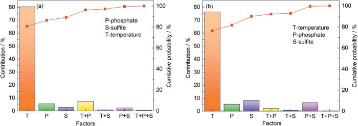
图5
环境因素对腐蚀速率影响权重
Fig.5
Influence weight of environmental factors on corrosion rate of 20#/20# steel (a) and 20#/316L steel welded joints (b)
电偶腐蚀中20#钢腐蚀速率数学模型如下:
其中,T为温度,℃;P为磷酸盐浓度,mg/L;S为亚硫酸盐浓度,mg/L。
2.3 四点弯曲应力腐蚀实验
对焊接接头腐蚀样片实验完成后进行腐蚀形貌的观察,腐蚀形貌如图6所示。图6a、c和e为20#/20#钢焊接头在实验环境中浸泡240、480和720 h之后的未去除腐蚀产物和去除腐蚀产物之后的宏观形貌。图6b、d和f为20#/316L钢焊接头在实验环境中浸泡240、480和720 h之后的未去除腐蚀产物和去除腐蚀产物之后的宏观形貌。图6中的红线框为焊接头的20#钢区域。结果显示,在焊接接头表面布满灰色或者黄色的铁锈。20#/20#钢焊接接头较容易发生全面的均匀腐蚀,有深灰色的铁锈和黄色的铁锈生成;20#/316L钢焊接接头,通常形成黄色的铁锈,在焊接接头的热影响区偏向于发生局部腐蚀甚至点蚀。在高静水压力环境下,更容易出现局部腐蚀,局部腐蚀的敏感性提高。
图6
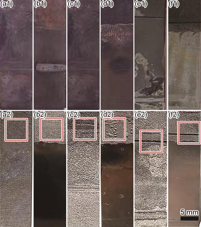
图6
不同时间腐蚀下20#/20#钢和20#/316L钢宏观形貌
Fig.6
Optical pictures of welded joints under simulated environment, with 20#/20# steel welded joints for 240 h (a), 480 h (c) and 720 h (e), and 20#/316L steel welded joints for for 240 h (b), 480 h (d) and 720 h (f)
图7
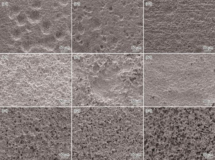
图7
20#/20#钢焊接头腐蚀不同时间的微观组织形貌
Fig.7
SEM images showing morphologies of 20#/20# steel welded joints in different regions (BM, HAZ, WM) after corrosion test: (a) 240 h, (b) 480 h, (c) 720 h
图8
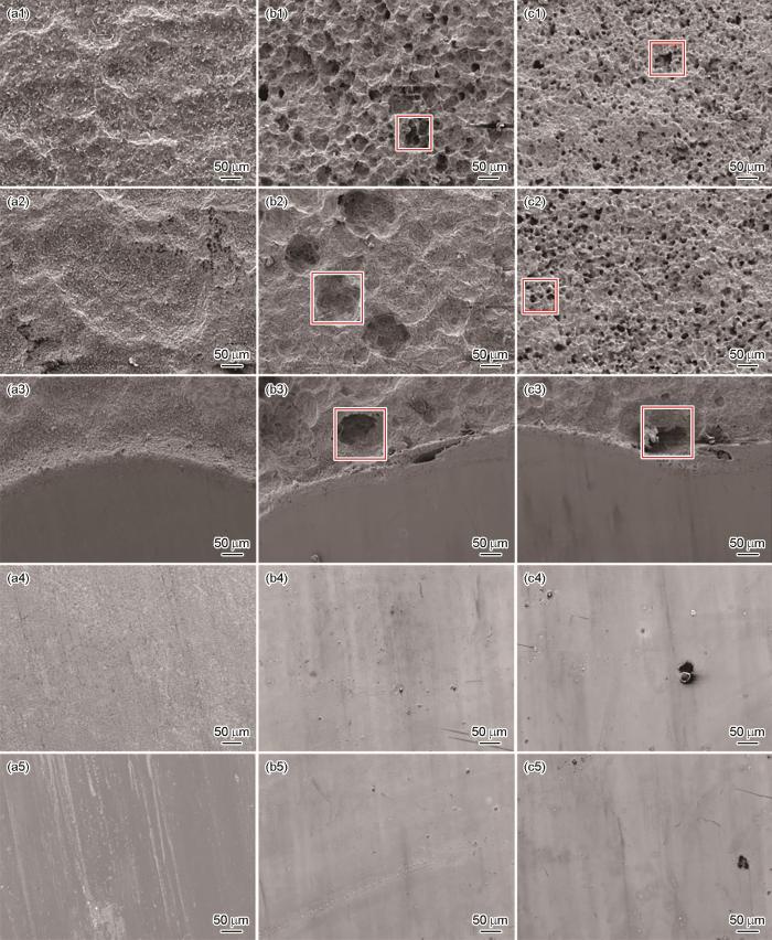
图8
20#/316L钢焊接头腐蚀不同时间的微观组织形貌
Fig.8
SEM images showing morphologies of 20#/316L steel welded joints in different regions (20#BM, 20#HAZ, WM, 316L HAZ, 316L BM) after corrosion for 240 h (a), 480 h (b) and 720 h (c)
浸泡720 h的20#/20#钢、20#/316L钢焊接接头热影响区腐蚀试样去除腐蚀产物后的截面SEM腐蚀形貌,如图9所示。图9a为20#/20#钢试样初始预制裂纹长度为670.9 µm,图9b显示20#/20#钢焊接接头试样浸泡实验完成后裂纹长度为694.7 µm,图9c显示20#/316L钢试样初始预制裂纹长度为683.5 µm,(图9d)显示20#/316L钢焊接接头试样实验完成后裂纹长度为702.4 µm,可以看出,经过720 h的浸泡后,20#/20#钢焊接接头以及20#/316L钢焊接接头预制的腐蚀坑深度均有所增大,20#/316L钢焊接接头明显比20#/20#钢焊接接头腐蚀速率更快,与前面环境因素对腐蚀速率影响结果相符。
图9
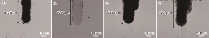
图9
20#/20#钢、20#/316L钢热影响区浸泡前后的截面SEM形貌
Fig.9
SEM images showing the morphologies of prefabricated cracks of 20#/20# (a, b) and 20#/316L (c, d) steel welded joints before and after corrosion test
图10
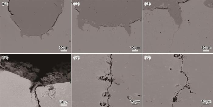
图10
20#/20#钢和20#/316L钢焊接接头四点弯曲浸泡720 h后热影响区截面SEM形貌
Fig.10
SEM images showing the morphologies of microstructure near the prefabricated cracks of (a) 20#/20# and (b) 20#/316L steel welded joints after corrosion test
热影响区裂纹形貌和微观组织(图11)显示,主裂纹沿晶界呈锯齿状延伸,几乎贯穿整个样品,裂纹宽度呈梯度变化,次生裂纹以主裂纹为轴线对称分布,呈现典型应力腐蚀开裂特征。热影响区裂纹附近的显微组织主要由铁素体、珠光体组成。特别在主裂纹内还可观测到一些腐蚀产物,证实环境介质沿晶界渗透引发应力腐蚀开裂的失效机制。
图11
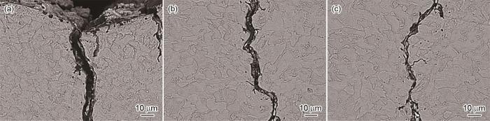
图11
20#/316L钢焊接接头四点弯曲实验720 h后热影响区截面组织形貌
Fig.11
SEM images of the microstructure near the prefabricated crack of 20#/316L steel welded joint after corrosion test (a-c)
图12
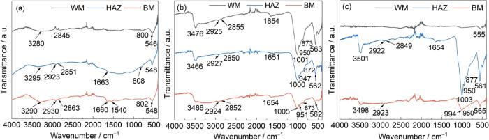
图12
20#/20#钢焊接接头表面腐蚀产物的FT-IR谱
Fig.12
FT-IR spectra of corrosion products of 20#/20# steel welded joints after corrosion of 240 h (a), 480 h (b) and 720 h (c)
在20#/20#样品的腐蚀初期,腐蚀产物主要有α-FeOOH和Fe3O4,但是随着腐蚀的继续,在腐蚀中期,产物中出现FePO4;在腐蚀的后期,焊缝处腐蚀产物主要是Fe3O4,基体处的腐蚀产物为Fe3O4以及α-FeOOH,热影响区腐蚀产物为Fe3O4。前期腐蚀差异不大,生成了以α-FeOOH和Fe3O4为主要产物的腐蚀产物膜,随着腐蚀时间的延长,前期较为致密的腐蚀产物膜被破坏,腐蚀速率逐步增加,锈层中稳定相(α-FeOOH)含量逐渐降低,在热影响区尤为明显。
图13
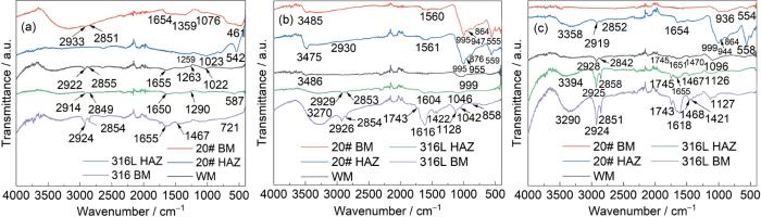
图13
20#/316L钢焊接接头表面腐蚀产物的FT-IR光谱
Fig.13
FT-IR spectra of corrosion products of 20#/316L steel welded joints after corrosion of 240 h (a), 480 h (b) and 720 h (c)
20#/20#钢焊接接头浸泡腐蚀240、480和720 h后的表面腐蚀产物的Raman光谱如图14a~c显示。在腐蚀初期(图14a),锈层中215、218和211 cm-1处的特征峰与α-FeOOH标准物相的特征峰一致,说明锈层中含有氧化物α-FeOOH。锈层的光谱在271、283和274 cm-1处也出现了γ-FeOOH的特征峰,与此同时,在508和505 cm-1处出现了Fe3O4的存在。注意到,锈层中在371和376 cm-1位置上也出现了α-FeOOH的特征峰。在腐蚀中期(图14b),锈层在664和661 cm-1出现了Fe3O4,在基体及焊缝968和956 cm-1位置出现强度较低的γ-FeOOH特征峰,在热影响区971 cm-1位置出现强度较高的γ-FeOOH特征峰。在腐蚀后期(图14c)锈层中出现α-FeOOH、Fe3O4等腐蚀产物。
图14
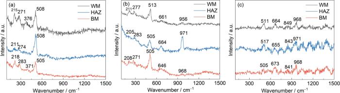
图14
20#/20#钢焊接接头表面腐蚀产物的Raman光谱
Fig.14
Raman spectra of corrosion products of 20#/20# steel welded joints after corrosion 240 h (a), 480 h (b) and 720 h (c)
图15

图15
20#/316L钢焊接接头表面腐蚀产物的Raman光谱
Fig.15
Raman spectra of corrosion products of 20#/316L steel welded joints after corrosion of 240 h (a), 480 h (b) and 720 h (c)
注意到,锈层中在371和376 cm-1位置上出现α-FeOOH的特征峰。在20#基体、20#热影响区、316L基体出现强度较低的Fe3O4。在腐蚀后期(图15c),锈层中出现α-Fe2O3、γ-FeOOH (1028、1043、1041、1056和1031 cm-1)等腐蚀产物。
3 结论
(1) 20#钢HAZ的显微组织主要由珠光体和大量条状铁素体组成。条状铁素体是腐蚀孔形核优先位置,同时,条状铁素体会提高金属中的晶界面积,增大腐蚀倾向。
(2) 20#/316L钢焊接头在极端水样180 ℃-30 mg/L NaH2PO4-150 mg/L NaSO3下的腐蚀速率(0.48 mm/a)约为正常水样105 ℃-0.1 mg/L NaH2PO4-0.5 mg/L NaSO3下(0.071 mm/a)的7倍,20#/20#钢焊接头在极端情况下的腐蚀速率(0.39 mm/a)约为正常运行状态(0.053 mm/a)的8倍。温度是影响腐蚀速率的决定性因素,而磷酸盐和亚硫酸盐的影响权重较小。
(3) 在腐蚀初期,腐蚀产物以α-FeOOH和Fe3O4为主;在腐蚀中期,腐蚀产物以α-FeOOH、Fe3O4和FePO4为主;在腐蚀后期,腐蚀产物以Fe3O4和FePO4为主,腐蚀产物对于腐蚀阶段的判断具有指导意义。
(4) 管路焊接接头处发生的应力腐蚀行为是由腐蚀环境和应力的耦合作用造成的。20#/20#钢焊接头,其均匀腐蚀速率过快,预制裂纹后,在焊接造成的残余应力和结构应力的作用下,导致裂纹萌生。而20#/316L钢焊接头,在组织结构和电偶腐蚀的共同作用下,其局部区域腐蚀速率过快,诱发应力腐蚀,裂纹开始萌生并发生扩展。随着裂纹持续沿截面扩展,并发展部分二次裂纹,最终造成焊接接头的失稳断裂。
参考文献
Failure analysis of the wall tubes of a water-tube boiler
[J].
Failure analysis of a superheater tube ruptured in a power plant boiler: Main causes and preventive strategies
[J].
Failure investigation of water wall tubes in a drum boiler of a thermal power plant
[J].
Corrosion failure analysis of the heat exchanger in a hot water heating boiler
[J].
Advancement of steam generation process in water tube boiler using Taguchi design of experiments
[J].
Metallurgical analysis of ASME SA213 T12 boiler vertical water-wall tubes failure
[J].
Creep rupture properties of welded joints of heat resistant steels
[A].
A comparison of creep rupture strength of ferritic/austenitic dissimilar weld joints of different grades of Cr-Mo ferritic steels
[J].
Creep rupture properties of welded joints of heat resistant steels
[J].
An evaluation of creep rupture strength of ferritic/austenitic dissimilar weld interfaces using cohesive zone modelling
[J].
Failure analysis of a reheater tube dissimilar metal weld failure in a 500 MW power plant
[J].
Failure of an ASTM A213 T12 steel tube of a circulating fluidized bed boiler
[J].
Failure analysis of waste heat boiler tubing caused by a high local heat flux
[J].
External corrosion of oil and gas pipelines: A review of failure mechanisms and predictive preventions
[J].
Corrosion of metallic biomaterials: A review
[J].
Corrosion behavior of AA6016/SM490 galvanic couple in NaCl-containing droplets: Effect of Fe species on galvanic corrosion acceleration
[J].
Comparison of electrochemical behavior between coarse-grained and fine-grained AISI 430 ferritic stainless steel by Mott-Schottky analysis and EIS measurements
[J].
Experimental and theoretical studies of benzothiazole derivatives as corrosion inhibitors for carbon steel in 1 M HCl
[J].
Deposit attack in tubes of power plant steam boilers
[J].
Phosphate induced stress corrosion cracking in a waterwall tube from a coal fired boiler
[J].
Failure analysis of a superheater tube ruptured in a power plant boiler: Main causes and preventive strategies
[J].
Mechanism of chlorine-induced stress corrosion cracking of two 304 SS heats in simulated marine environment through in situ X-ray tomography and diffraction: Role of deformation induced martensite and crack branching
[J].
Factors affecting stress corrosion cracking susceptibility of alloy 600 MA steam generator tubes
[J].
Structural health monitoring of stainless-steel nuclear fuel storage canister using acoustic emission
[J].
Investigation of multi-factor stress corrosion cracking failure of safe-end feedwater lines of submarine power system
[J].
