


磨损腐蚀通常发生在腐蚀介质中,是力学、化学和电化学因素综合作用的结果,是材料降解的关键因素[12,13]。Zhou等[14]采用二维超声表面抛光技术构建了梯度纳米结构的铝合金,阻碍了磨损过程中的位错滑动,减少了累积剪切,提高了磨损腐蚀性能。Chen等[15]采用针盘式摩擦计研究了LY12铝合金在人工海水中的磨蚀,结果表明,电流密度和开路电位的阴极位移提高了两个数量级,电位大于-0.4 V时,材料损失量随电位的增加递增,表明磨损和腐蚀之间存在协同作用。磨损腐蚀造成材料的损耗,远大于磨损和腐蚀的简单叠加,而是协同过程,称为协同效应[16~18]。一方面,腐蚀效应加速磨损,另一方面,磨损加速腐蚀[12]。尽管现有研究探讨了铝合金在磨损腐蚀过程中的相互作用,但这些研究大多集中在静态腐蚀方面,对于磨蚀机理的全面深刻揭示仍需大量细致的研究工作。
本文研究了7075铝合金的磨损腐蚀行为,探究了加压载荷和摩擦频率对其磨蚀行为的影响机制。将电化学工作站和磨损腐蚀试验机联合使用,通过改变摩擦频率和加压载荷进行磨蚀实验。实验在模拟海洋环境的3.5% (质量分数) NaCl中进行。采用激光共聚焦显微镜和扫描电子显微镜对磨蚀轨道形貌进行表征和分析。最终基于实验结果探寻7075铝合金的磨损-腐蚀交互机理,量化磨蚀过程中的力学、化学和电化学间的交互关系。
1 实验方法
实验采用7075铝合金(轧制方向为横向),其化学成分(质量分数,%)为:Zn 5.69、Mg 2.36、Cu 1.56、Fe 0.15、Si 0.06、Mn 0.02、Cr 0.2、Ti 0.04、Zr 0.01、B 0.0009、Pb 0.001、Sn 0.001、Ti + Zr 0.05、余量为Al。将试样切割成10 mm × 10 mm × 3 mm的块状,用Cu线连接嵌入环氧树脂中,留下1 cm2的工作表面。实验前,依次采用不同粒度的SiC的砂纸、1.0 μm水性抛光膏进行机械抛光,最后用无水乙醇进行超声清洗,干燥待用。
在磨损腐蚀实验中,需要对摩擦过程中的腐蚀行为同步检测,图1为磨损腐蚀实验装置。电化学测试在电化学工作站(BioLogic SP-150)上进行,其中三电极体系包括:饱和甘汞电极(SCE,0.242 V vs.氢标准电极)为参比电极(RE),Ag/AgCl为参比电极(RE),Pt丝为对电极(CE),试样表面为工作电极(WE),腐蚀介质为3.5% NaCl溶液。为了排除对偶件对电位的干扰,避免不同金属接触时因电位差形成电偶电池而影响结果,选用直径为6.35 mm的Si3N4陶瓷球固定于对磨销下端(Si3N4陶瓷球因其高硬度、耐热性和化学稳定性等特性减少了电化学腐蚀和电流干扰,使电化学实验结果更准确,但因其摩擦系数低,可能会导致实验测得的摩擦系数较低)。
图1
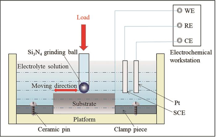
开路电位(OCP)总时长设置7200 s,前1800 s摩擦头静置,可得到摩擦前试样的静态开路电位的变化趋势,在3600 s时开始加压载荷,磨损期间测量摩擦系数(COF),后1800 s静置不摩擦,可获得静态开路电位恢复趋势。动电位极化测试设置为-1.4~0.4 V (vs. OCP),扫描速率为1 mV/s,获得铝合金在摩擦过程中的自腐蚀电位和腐蚀电流密度等参数的信息。实验均在室温下进行,每组进行3次平行试验。摩擦头单次行程均为4 mm、摩擦时间为3600 s。在不同摩擦频率的实验中,固定载荷为5 N,摩擦频率为0.01、0.10、0.25、0.50、0.75和1.00 Hz。不同加压载荷实验中,摩擦频率固定1 Hz,施加载荷分别为5、10、20、30和40 N。通过激光共聚焦显微镜(CLSM,Keyence VK-250)对磨蚀后的试样表面进行三维形貌观察,统计分析磨蚀过程中损失体积。采用扫描电子显微镜(SEM,ZEISS Gemini300)观察,采用SEM自带的电子能谱仪(EDS,Oxford)分析磨损区域成分。
2 结果与讨论
2.1 摩擦系数及开路电位
图2a和b为7075铝合金在不同摩擦频率和不同加压载荷条件下COF值的变化。从图2a可以看出,频率为0.01 Hz时,COF值增加缓慢,在800 s左右达到稳定,平均值为0.325,波动最为剧烈。当摩擦频率提升至0.10 Hz时,COF的平均值增加至0.41,但波动明显减弱。在摩擦频率为0.25~1.00 Hz的范围内,COF曲线的波动范围明显减小。图2b为1 Hz恒定摩擦频率下加压载荷对COF值的影响统计图。结果表明,从5 N增加到40 N,初始COF值呈现下降趋势,从0.58降低到0.42。这主要是由于随着载荷增加,摩擦副之间的实际接触面积逐渐增大,接触应力随之降低,从而产生了初始COF值随载荷增加而减小的现象。值得注意的是,当载荷为30和40 N时,COF值的增长速率明显高于低载荷,这主要是因为在大载荷下,磨损区累积了大量的碎屑,切向阻力增大,导致COF值上升速率更大。
图2
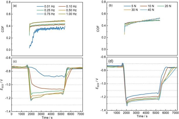
图2
7075铝合金磨损腐蚀的COF和OCP曲线
Fig.2
COF (a, b) and OCP (c, d) curves of 7075 Al-alloy during tribocorrosion at different frequencies (a, c) and applied loads (b, d)
图2c和d展示了7075铝合金OCP随摩擦频率和加压载荷的变化。当摩擦开始的一瞬间,OCP骤减,此现象被称为阴极移位[19]。这是由于摩擦导致Al表面氧化膜破坏,基材直接暴露于溶液中,增加了电化学活性。对比不同条件下的阴极移位可以发现,随着摩擦作用的增加,开路电位会急剧负移。此外,还可以发现OCP值在达到最低点后呈现回升的趋势,这是由于摩擦过程中产生了大量的腐蚀产物和磨屑,从而阻止了与磨副之间的直接接触,使得腐蚀现象有所缓和。当摩擦进行到5400 s结束时,由于摩擦条件消失,铝合金的磨损区域迅速钝化,导致电位突然正移,这被称为阳极移位。此外,从图中还可以看出,阳极移位曲线分成两个阶段,第一阶段的移位是由于摩擦副移除的瞬间,新鲜金属表面快速被氧化;第二阶段的移位反映了铝合金表面钝化膜的发展过程。
2.2 动电位极化曲线
图3为不同摩擦频率和加压载荷条件下的动电位极化曲线,采用E-Clab软件进行的Tafel拟合结果示于表1。可见,7075铝合金在静态条件下的腐蚀电位为-0.71 V,腐蚀电流密度2.24 μA/cm2。从图3中可以看到摩擦过程中铝合金极化曲线的阳极区出现了近似平台的区域,即电流随着电位升高近似保持恒定,表明出现了钝化现象[8,20,21]。这可能是由于磨蚀过程中产生的难溶性产物附着在基材表面,形成了钝化层,保护裸露表面减缓了金属的腐蚀[8,22~24]。摩擦过程导致7075铝合金的自腐蚀电流发生负移,这与开路电位结果一致。此外,电流密度显著增加,提高了2~3个数量级,这归因于摩擦对基材表面氧化层的破坏,从而使得磨损区域处于活化状态。在这种情况下,磨损区域的高电化学活性与为磨损区域之间形成微电偶效应,加速了磨损区域的腐蚀速率[25]。当电位超过某一临界值时,电流密度随着电位升高急剧增加,表明出现了钝化膜击穿现象,此时所对应的电位称为击穿电位或点蚀电位(Epit)。这一过程中,Cl-起了很大的促进作用,由于Cl-尺寸较小,它对点蚀非常敏感,可以穿透表面,具有诱发和加重点蚀的作用。
图3
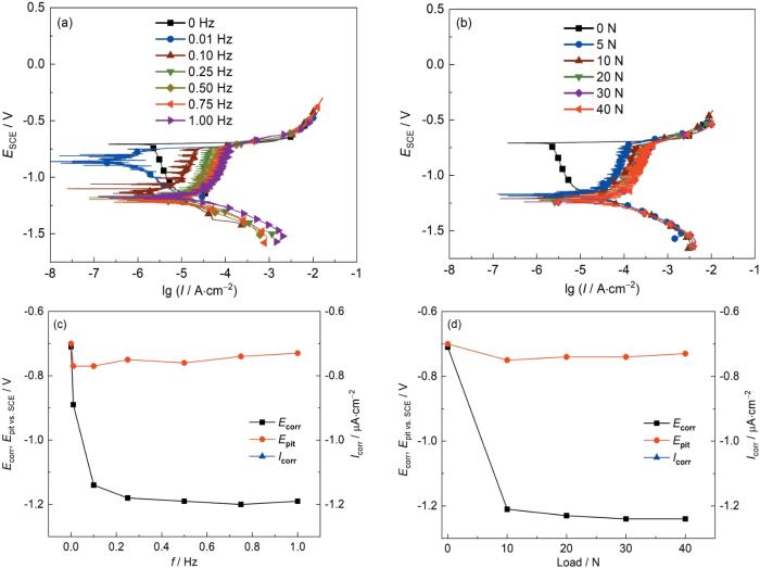
图3
7075铝合金磨损腐蚀的极化曲线和Tafel拟合数据
Fig.3
Potentiodynamic polarization curves (a, b) and fitting date (c, d) of 7075 Al-alloy during tribo-corrosion at different frequencies (a, c) and applied loads (b, d)
表1 7075铝合金的动电位极化曲线参数
Table 1
| f / Hz | Load / N | Ecorr vs. SCE / V | Epit vs. SCE / V | Icorr / μA·cm-2 |
|---|---|---|---|---|
| 0 | 0 | -0.71 | -0.70 | 2.24 |
| 0.01 | 5 | -0.89 | -0.77 | 0.69 |
| 0.10 | 5 | -1.14 | -0.77 | 2.88 |
| 0.25 | 5 | -1.18 | -0.75 | 2.24 |
| 0.50 | 5 | -1.19 | -0.76 | 8.71 |
| 0.75 | 5 | -1.20 | -0.74 | 12.59 |
| 1.00 | 5 | -1.19 | -0.73 | 14.45 |
| 1.00 | 10 | -1.21 | -0.75 | 17.78 |
| 1.00 | 20 | -1.23 | -0.74 | 31.62 |
| 1.00 | 30 | -1.24 | -0.74 | 40.74 |
| 1.00 | 40 | -1.24 | -0.73 | 56.23 |
2.3 磨痕形貌分析
图4
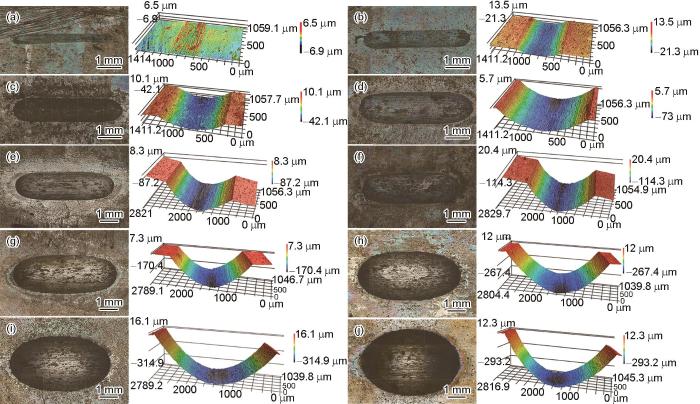
图4
7075铝合金磨损区域3D形貌
Fig.4
3D morphologies of the wear tracks of 7075 Al-alloy after tribocorrosion at different frequencies and loads: (a) 0.01 Hz, 5 N, (b) 0.05 Hz, 5N, (c) 0.10 Hz, 5 N, (d) 0.50 Hz, 5 N, (e) 0.75 Hz, 5 N, (f) 1.00 Hz, 5N, (g) 1.00 Hz, 10 N, (h) 1.00 Hz, 20 N, (i) 1.00 Hz, 30 N, (j) 1.00 Hz, 40 N
图5
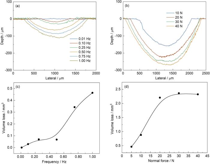
图5
7075铝合金磨痕处的截面轮廓及磨损体积
Fig.5
Cross-section profiles of the wear tracks (a, b) and wear volumes (c, d) of 7075 Al-alloy after tribo-corrosion at different frequencies (a, c) and applied loads (b, d)
图6为7075铝合金磨痕处的微观形貌分析结果。当摩擦作用较小时(5 N-0.01 Hz和5 N-0.10 Hz),磨损区域出现了断续的犁沟和凹坑,表面覆有少量的磨损颗粒,这些磨屑在腐蚀和磨损的共同影响下,经过反复碾压和堆叠,使得原本的两体摩擦转变为三体摩擦,磨屑起到了磨粒的作用,这是磨粒磨损的典型特征[26,27]。随着摩擦作用加强,往复运动产生的疲劳作用加剧了基材内部塑性流动,微峰易于产生屈服和疲劳,磨屑在磨损区域边缘堆积,磨损区域表面存在大颗粒撕裂现象,这是黏着磨损[28]。EDS结果表明(表2),磨损区域主要由金属氧化物组成[29~32],磨屑中含有Cu、Fe、Mg和Zn等元素,这些元素在铝合金中形成了如Mg2Si、Al7Cu2Fe和Al23Fe4Cu等金属间化合物。因为金属间化合物与基体之间的电化学活性不同,存在电流效应,极易形成电偶,从而加速或抑制铝基材的溶解,所以金属间化合物在铝合金的耐磨蚀性能中起到重要作用。
图6
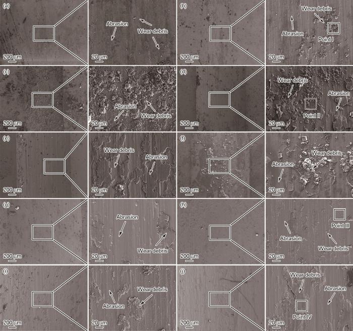
图6
7075铝合金磨损腐蚀的磨损区域SEM图像
Fig.6
SEM images of the wear tracks of 7075 Al-alloy after tribocorrosion at different frequencies and loads: (a) 0.01 Hz, 5 N, (b) 0.05 Hz, 5 N, (c) 0.10 Hz, 5 N, (d) 0.50 Hz, 5 N, (e) 0.75 Hz, 5N, (f) 1.00 Hz, 5 N, (g) 1.00 Hz, 10 N, (h) 1.00 Hz, 20 N, (i) 1.00 Hz, 30 N, (j) 1.00 Hz, 40 N
表2 图6中4个标记点处EDS成分分析结果 (mass fraction / %)
Table 2
| Element | O | Al | Si | Cl | Mn | Fe | Cu | Zn | Mg |
|---|---|---|---|---|---|---|---|---|---|
| Point Ⅰ | 49.96 | 41.95 | 0.61 | 4.06 | 0.00 | 0.46 | 0.24 | 1.21 | 1.04 |
| Point Ⅱ | 58.53 | 35.03 | 0.10 | 3.48 | 0.00 | 0.00 | 0.29 | 1.07 | 1.50 |
| Point Ⅲ | 2.67 | 87.77 | 0.11 | 0.05 | 0.24 | 0.00 | 1.38 | 5.62 | 2.14 |
| Point Ⅳ | 26.41 | 64.86 | 0.05 | 1.29 | 0.09 | 0.00 | 1.03 | 4.69 | 1.59 |
2.4 磨损腐蚀耦合作用分析
7075铝合金在质量分数为3.5%NaCl溶液中的磨蚀过程中,材料表面力学、化学和电化学相互协同,导致材料损失远大于这些过程单独作用的总和。磨损过程分为纯机械损耗(W0)、纯腐蚀损耗(C0)和腐蚀与磨损的交互作用(S) 3类。总损耗(T)是协同分量(S)、纯机械损耗(W0)和纯腐蚀损耗(C0)的总和。协同分量(S)是腐蚀和磨损的交互作用,即磨损加速腐蚀(ΔCw)与腐蚀加速磨损(ΔWc)的加和。由于总磨损分量(Wc)不是纯机械损耗(W0),还包含腐蚀加速磨损(ΔWc)。此外,总腐蚀分量(Cw)也不是纯腐蚀损耗(C0),还包含磨损加速腐蚀(ΔCw)。可推导公式如下[33]:
或
式中,T为材料的总损耗,mm3;W0为纯机械磨损导致的材料损耗,mm3;C0为腐蚀导致的材料损耗,mm3;ΔCw为磨损加速腐蚀造成的材料损耗,mm3;ΔWc为腐蚀加速磨损导致的材料损耗,mm3。其中C0和ΔCw可由Faraday公式计算,计算过程为:
图7
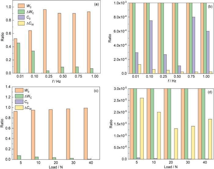
图7
7075铝合金磨损腐蚀的各组分损失占比
Fig.7
Loss ratios of various wear components for 7075 Al-alloy after tribo-corrosion conditions at different frequencies (a, b) and applied loads (c, d) (Fig.7b and Fig.7d are enlarged views of the red dashed boxes in Fig.7a and Fig.7b, respectively)
表3 不同磨损腐蚀条件下各磨损组分值
Table 3
| f / Hz | Load / N | T / mm3 | W0 / mm3 | C0 / mm3 | ΔWc / mm3 | ΔCw / mm3 | W/C | ΔWc/W0 |
|---|---|---|---|---|---|---|---|---|
| 0.01 | 5 | 0.010 | 0.01 | 2.70 × 10⁻⁷ | 0.01 | 1.00 × 10⁻⁷ | > 10 | < 1 |
| 0.10 | 5 | 0.040 | 0.02 | 2.70 × 10⁻⁷ | 0.01 | 2.10 × 10⁻⁶ | > 10 | < 1 |
| 0.25 | 5 | 0.101 | 0.10 | 2.70 × 10⁻⁷ | 0.01 | 4.80 × 10⁻⁶ | > 10 | < 1 |
| 0.50 | 5 | 0.241 | 0.22 | 2.70 × 10⁻⁷ | 0.02 | 5.90 × 10⁻⁶ | > 10 | < 1 |
| 0.75 | 5 | 0.331 | 0.30 | 2.70 × 10⁻⁷ | 0.03 | 8.00 × 10⁻⁶ | > 10 | < 1 |
| 1.00 | 5 | 0.461 | 0.43 | 2.70 × 10⁻⁷ | 0.03 | 1.20 × 10⁻⁵ | > 10 | < 1 |
| 1.00 | 10 | 0.881 | 0.84 | 2.70 × 10⁻⁷ | 0.04 | 1.80 × 10⁻⁵ | > 10 | < 1 |
| 1.00 | 20 | 2.201 | 2.12 | 2.70 × 10⁻⁷ | 0.08 | 2.90 × 10⁻⁵ | > 10 | < 1 |
| 1.00 | 30 | 2.361 | 2.31 | 2.70 × 10⁻⁷ | 0.06 | 3.20 × 10⁻⁵ | > 10 | < 1 |
| 1.00 | 40 | 2.321 | 2.30 | 2.70 × 10⁻⁷ | 0.02 | 4.00 × 10⁻⁵ | > 10 | < 1 |
借助Stack等[34]的冲蚀-腐蚀状态定义方法,利用总磨损贡献与总腐蚀贡献的比值将磨损腐蚀状态定义如下:
磨损腐蚀不是简单的机械摩擦磨损和电化学腐蚀的叠加,其中也包含了二者的交互作用。Stack等[34]提出协同效应,将“协同”效应定义为:
在较小的摩擦作用下(5 N-0.01 Hz和5 N-0.10 Hz)时,T和W0均很小,W0占比52.26%~66.40%,腐蚀加速磨损导致的ΔWc达到45.69%~33.59%的最高占比。当摩擦作用进一步增大时,W0迅速增大,进入严重磨损阶段,占比90.39%~99.21%,但此时ΔCw占比减小。综上所述,7075铝合金在磨蚀过程中的材料损耗不是静态腐蚀和机械磨损的简单叠加。
3 结论
(1) 在不同摩擦频率和不同加压载荷条件下COF值均有不同程度的上升和波动范围的增加。摩擦频率和加压载荷影响OCP阴极移位的机制不同,频率增加使基材再钝化时间减少,磨损区域保持活跃状态,增加电化学活性,而加压载荷则是通过改变磨损区域面积和电偶联效应来影响OCP阴极移位。
(2) 相比于静态的腐蚀条件,铝合金在摩擦条件下电流密度显著增加了2~3个数量级,摩擦导致基材表面的致密氧化层破坏,磨损表面相较于为磨损表面展现出更高的电化学活性。
(3) 高硬度Si3N4磨球压入7075铝合金并犁削其表面,导致铝合金表面出现平行于摩擦方向的犁沟、脱落磨屑和边缘材料堆积。随摩擦增大,磨痕变宽、沟槽加深和塑性变形加剧。摩擦作用较低时为磨粒磨损,摩擦作用较高时则为黏着磨损,表现为大颗粒撕裂形貌。
(4) 摩擦腐蚀导致材料的损失不是静态腐蚀和机械磨损的简单叠加,力学因素是导致磨损腐蚀失重的主要原因,但腐蚀与磨损之间的协同交互作用同样重要。尤其是腐蚀促进磨损。在较小摩擦作用下时,纯机械磨损占比52.25%~66.40%,腐蚀加速磨损达到45.69%~33.59%的最高占比。当摩擦作用进一步增大时,W0占比90.39%~99.21%,进入严重磨损阶段。
参考文献
Surface remelting treatment of 7075 aluminum alloy—microstructural and technological aspects
[J].
Investigations on electrochemical corrosion behavior of 7075 aluminum alloy with femtosecond laser modification
[J].
Interface microstructure and mechanical properties of Ni-Co-P alloy coatings modified carbon fibres reinforced 7075Al matrix composites
[J].
Effect of micro-nano hybrid SiCp on microstructure and mechanical properties of 7075Al alloy
[J].
Deposition behavior of the gas-atomized 7075Al and TiB2/7075Al composite powders during cold spraying
[J].
Understanding the multifaceted incorporation of a Zn-maize cob nanoparticle composite coating of mild steel: Anti-wear, anti-corrosion, and oxidation resistance
[J].
Corrosion and wear resistance improvements in NiCu alloys through flame-grown honeycomb carbon and CVD of graphene coatings
[J].
Enhanced wear and corrosion resistance of wire-arc additive manufactured Al-Cu alloy by friction stir processing
[J].
Visually monitoring of wear damage and interfacial corrosion in lubricant coating enabled by MXene@Rhodamine B fluorophores
[J].
Corrosion wear properties of Fe-based amorphous coatings sprayed by supersonic atmospheric plasma spraying
[J].
Effects of Mn addition on wear and corrosion resistances of AlCoCrFeNi high-entropy alloy coating sprayed by HVOF
[J].
Corrosion and passivity of metals and coatings
[A]. Landolt D, Mischler S.
An in-situ study on the dissolution of intermetallic compounds in the Al-Zn-Mg-Cu alloy
[J].
Research on the construction of gradient nanostructure and anti-tribocorrosion behavior of aluminum alloy surface
[J].
Tribocorrosion behavior of LY12 aluminum alloy in artificial seawater solution
[J].
Corrosion and tribocorrosion behaviors of AISI 316 stainless steel and Ti6Al4V alloys in artificial seawater
[J].
Effect of hydrostatic pressure on the corrosion behaviour of Ni-Cr-Mo-V high strength steel
[J].
Wear behaviors and wear mechanisms of several alloys under simulated deep-sea environment covering seawater hydrostatic pressure
[J].
Influence of microstructure evolution on tribocorrosion of 304SS in artificial seawater
[J].
The influence of secondary aging on the microstructure and corrosion resistance of Al-Zn-Mg-Cu alloy
[J].
Electrochemical corrosion influencing the Al beryl alloy system subjected to extrusion process
[J].
Microstructure, wear and corrosion resistance mechanism of as-cast lightweight refractory NbMoZrTiX (X = Al, V) high-entropy alloys
[J].
Plasma-sprayed Al-based coating with WC-addition for excellent corrosion resistance and enhanced wear protection of Mg alloys
[J].
Effects of post heat treatment on key T-phase evolution and the matching mechanism of enhanced strength-toughness, wear resistance and corrosion resistance in Al-Mg-Zn-(Cu-Er-Zr) alloy by laser powder bed fusion
[J].
Insights on the Al-Cu-Fe-Mn intermetallic particles induced pitting corrosion of Al-Cu-Li alloy
[J].
Effect of Al-Fe-Mn-Si particle characteristics on the growth morphology and corrosion resistance of anodic oxide film on AA3003 aluminium alloy
[J].
Optimized nanoporous alumina coating on AA3003-H14 aluminum alloy with enhanced tribo-corrosion performance in palm oil
[J].
A round robin on combined electrochemical and friction tests on alumina/stainless steel contacts in sulphuric acid
[J].
Microstructural characterization and high-temperature wear behavior of refractory niobium-carbide growth in intermetallic iron-aluminide coatings
[J].
Structural, dry sliding wear and tribocorrosion behaviors of the Mo-Si-B intermetallic alloys
[J].
Fabrication and wear behavior of TiC/TiB2-reinforced NiAl intermetallic matrix composites
[J].
Wear characteristics and performance in side milling of Ti2AlNb intermetallic alloys with coated and uncoated end mills
[J].
Micro-abrasion-corrosion of a Co-Cr/UHMWPE couple in Ringer's solution: An approach to construction of mechanism and synergism maps for application to bio-implants
[J].
