


锌镁铝镀层钢板具有较好的耐蚀性,在汽车、家电等行业具有应用前景。基于此,本研究通过水热合成法制备纳米Zr-MOF材料,在此基础上通过水热法在Zr-MOF材料表面负载纳米CeO2探究复合材料的形貌和结构特性,将制备的复合材料作为填料加入环氧树脂涂层中以提高环氧树脂涂层的力学性能和对锌镁铝镀层钢板的防护性能,为金属腐蚀防护提供更为有效和便捷的手段。
1 实验方法
1.1 实验材料
实验基体为首钢生产的锌镁铝镀层钢板,镀层成分为1.5%Mg-1.5%Al-97%Zn,简称ZMA钢。试片尺寸为25 mm × 25 mm × 5 mm。所用的四氯化锆和硝酸铈均购于北京迈瑞达公司;对苯二甲酸、乙酸、乙二醇和氨水均购于北京百灵威公司;N,N-二甲基甲酰胺、无水乙醇和正丁醇均购于北京通广公司;二甲苯购于上海麦克林公司;实验所用环氧树脂和固化剂均购于深圳明德,环氧树脂型号为E-44,固化剂型号为651和T-31。
1.2 Zr-MOF材料制备
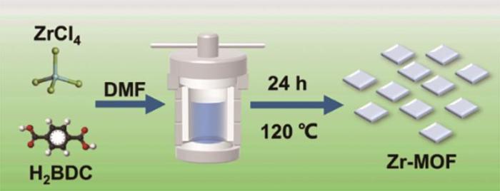
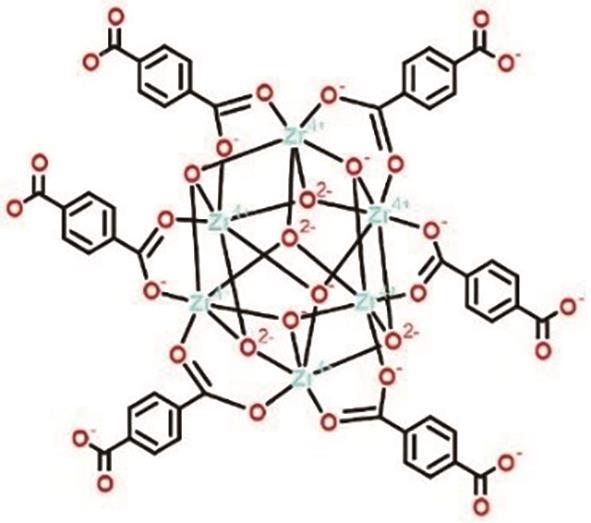
采用溶剂热法合成Zr-MOF,合成过程如图1所示。首先,用分析天平称量699 mg ZrCl4和166 mg对苯二甲酸加入含有100 mL N-N二甲基甲酰胺的烧杯中,然后在溶液中加入30 mL的乙酸用以调节溶液pH。溶液搅拌30 min后倒入高压釜中,将高压釜放入烘箱在120 ℃的温度下反应24 h。待水热釜冷却到室温后,用离心机对浑浊液进行离心,调节温度为60 ℃干燥12 h,得到Zr-MOF材料。
图1
1.3 CeO2@Zr-MOF材料制备
采用水热法合成CeO2@Zr-MOF,合成过程如图2所示。首先将0.5 g上述制备的Zr-MOF粉末加入烧杯中,向烧杯中加入30 mL蒸馏水,持续搅拌2 h,超声30 min使MOF均匀分散在烧杯中,随后向烧杯中加入20 mL乙二醇和30 mL氨水。之后称量1 g Ce(NO3)3加入烧杯中,再向烧杯中加入90 mL蒸馏水,搅拌均匀后将溶液置于反应釜中,将反应釜放入烘箱在100 ℃的高温下加热反应24 h。待高压釜冷却到室温后,倒去上清液,将剩下的浑浊液倒入离心管,用离心机收集白色产物,调节温度为60 ℃干燥12 h。烘干后将样品放置于马弗炉中450 ℃焙烧3 h,研磨,得到CeO2@Zr-MOF材料。
图2

图2
CeO2@Zr-MOF的制备流程示意图
Fig.2
Schematic flow diagram of the preparation of CeO2@Zr-MOF
1.4 涂层制备
首先用去污粉清洗镀层钢片2~3次以去除金属表面的油污物,接着用乙醇擦洗,吹干待用。
涂层的制备:(1) 烧杯中加入分散剂二甲苯3 g和正丁醇2 g,混合均匀后分别加入0.5%、1%、2%的Zr-MOF (或CeO2@Zr-MOF)填料,之后将烧杯超声15 min使得填料分散完全。涂层中填料加入的比例过多时会造成填料在环氧树脂涂层中分散不均匀从而形成团聚,破坏涂层整体的完整性,反而不利于提升涂层的耐蚀性能,一般填料加入比例不大于2%[13]。因此本实验选用填料加入比例为0.5%、1%及2%。(2) 加入环氧树脂E-44 10 g搅拌10 min混合均匀。(3) 加入固化剂2.5 g 651和1 g T-31,将混合物搅拌10 min搅拌均匀。(4) 混合物室温放置30 min后用80 μm涂覆棒将其均匀地涂覆在镀层钢板上。涂覆完成后将钢板室温静置72 h固化。测试涂层干膜厚度为(80 ± 5) μm。
1.5 测试与表征
使用TENSOR27型Fourier红外光谱仪(FTIR)对所制备的材料化学结构进行测试,扫描范围为400~4000 cm-1。采用Ultima IV X射线衍射仪(XRD)对材料进行测试,扫描范围为5°~90°。采用S4800扫描电子显微镜表征材料的微观形貌。采用Talos F200S型高分辨透射电镜(TEM)对材料进行观察并进行能谱分析(EDS)。采用X射线光电子能谱(XPS)测试样品的元素及氧化价态。采用SSA-6000比表面积分析仪测试材料的孔径分布和比表面积。采用Fischer HM 2000显微硬度计测试复合涂层的硬度。载荷为500 mN,加载时间为20 s。采用PosiTest Pull-off附着力测试仪测试复合涂层在金属基体上的附着力。使用Interface 1000电化学工作站测试复合涂层的电化学阻抗谱。采用三电极体系,工作电极为涂覆涂层的钢板,参比电极为饱和甘汞电极,辅助电极为铂电极。其中工作电极测试面积为1 cm2。将整个电极体系置于3.5% (质量分数) NaCl水溶液环境中。在测试电化学阻抗谱(EIS)之前,测试开路电位直到其稳定后进行EIS测试,EIS参数设置为105~10-2 Hz,正弦波幅值:10 mV。为减小实验人工误差和机器误差,每个测试样品设置3个平行试样。将所得EIS结果使用Zsimpwin软件进行等效电路拟合,获得相关参数。
2 结果与讨论
2.1 CeO2@Zr-MOF复合材料的微观形貌结构
图3为CeO2@Zr-MOF的SEM形貌图,由图可见,合成的CeO2@Zr-MOF颗粒形貌较为规整,粒径在200 nm左右,大部分颗粒相对完整,并互相堆叠在一起。
图3
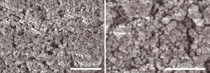
图3
CeO2@Zr-MOF不同放大倍数时的SEM图像
Fig.3
SEM images of CeO2@Zr-MOF in different magnification: (a) low image, (b) high image
图4
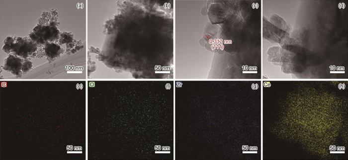
图4
CeO2@Zr-MOF不同放大倍数时的TEM图及TEM-EDS结果
Fig.4
TEM images of CeO2@Zr-MOFin different magnification(a-d) and TEM-EDS results of CeO2@Zr-MOF (e-h): (e) carbon, (f) oxygen, (g) zirconium, (h) cerium
2.2 CeO2@Zr-MOF复合材料的组织结构分析
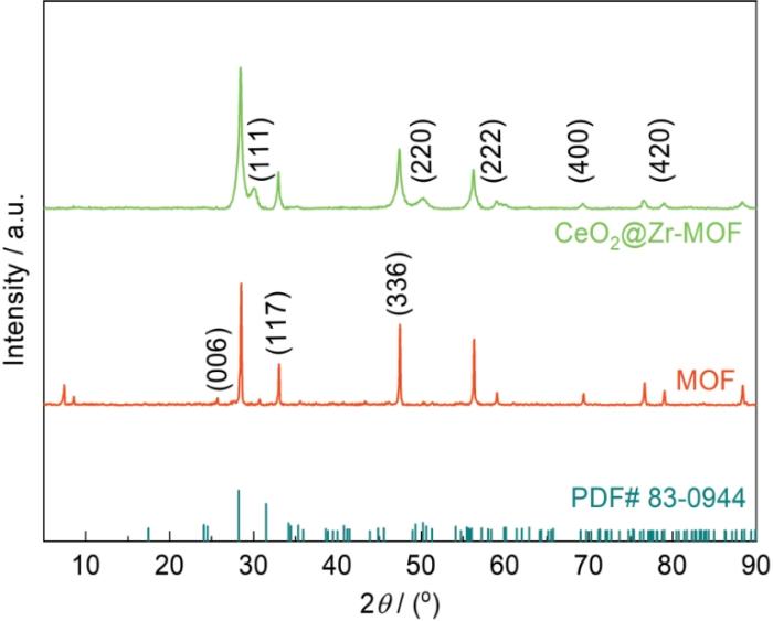
2.2.1 XRD测试
图5
2.2.2 FTIR测试
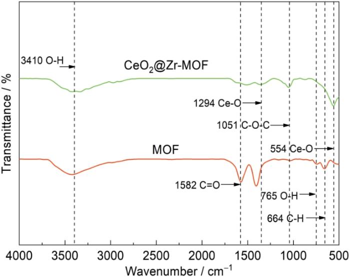
将合成的CeO2@Zr-MOF材料进行红外光谱测试,结果如图6所示。由图可见,CeO2@Zr-MOF有多个特征峰。其中在3410 cm-1处的特征峰为H2O中的O-H伸缩振动吸收峰;在2950 cm-1处出现特征峰,但不明显,为MOF的C-H特征峰;在1582 cm-1处的特征峰为MOF的C=O吸收峰;在765 cm-1处的特征峰为MOF中O-H基团的振动特征峰;在664 cm-1处的特征峰为MOF中C-H基团的振动特征峰。以上特征峰均属于Zr-MOF的特征峰。同时CeO2@Zr-MOF复合材料的图谱出现了新的吸收峰。其中在1294和554 cm-1处的特征峰为CeO2中Ce-O基团的振动特征峰,表明复合材料中CeO2的成功合成[14~17]。
图6
2.2.3 XPS测试
通过XPS进一步分析CeO2@Zr-MOF材料的元素组成,结果如图7所示。从图7a可以看出复合材料分别有4个峰位,分别是O 1s、C 1s、Zr 3d以及Ce 3d,符合CeO2@Zr-MOF的XPS图谱。从图7b的Zr的峰位图可以看出,Zr 3d能谱曲线拟合为两个特征峰,位于184.5与182.1 eV处,分别对应Zr 3d3/2轨道与Zr 3d5/2轨道。从图7c的Ce的峰位图可以看出,Ce 3d高分辨能谱曲线拟合为6个特征峰,分别位于917.2、907.6、901.2、899.4、888.2和883.1 eV处[17]。其中位于917.2、907.6与901.2 eV处的特征峰对应Ce 3d3/2轨道,位于899.4、888.2与883.1 eV处的特征峰对应Ce 3d5/2轨道。而这6种特征峰均为Ce4+特征峰,综合上述结果表明CeO2在MOF上成功负载。
图7

图7
CeO2@Zr-MOF材料的XPS总谱图及Zr 3d和Ce 3d高分辨率XPS谱图
Fig.7
XPS spectrum of CeO2@Zr-MOF material (a), Zr 3d high-resolution XPS spectrum of CeO2@Zr-MOF material (b) and Ce 3d (c)
采用氮气吸脱附等温线测定CeO2@Zr-MOF复合材料的比表面积和孔径分布,如图8所示。CeO2@Zr-MOF复合材料等温线为Type-Ⅳ等温线,吸附脱附等温线不重合,表明吸附脱附不完全可逆,因此会形成迟滞效应。同时观察CeO2@Zr-MOF的孔径分布图可以看出CeO2@Zr-MOF孔径主要分布在5~20 nm之间,通过Barrett-Joyner-Halenda模型分析得出所合成的CeO2@Zr-MOF平均孔半径为9.18 nm,表明所合成的CeO2@Zr-MOF含有一部分介孔结构。对所合成的CeO2@Zr-MOF的比表面积采用Brunauer-Emmett-Teller方法计算得出其BET平均比表面积为99.480 m2/g,表明CeO2@Zr-MOF具有较大的比表面积。CeO2@Zr-MOF材料的孔数量较多且孔结构均匀,稳定性好,具有更强的负载能力。
图8
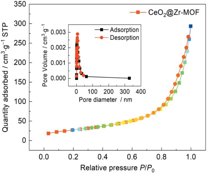
图8
CeO2@Zr-MOF的氮气吸附脱附曲线
Fig.8
Nitrogen adsorption-desorption curve for CeO2@Zr-MOF
图9
2.3 CeO2@Zr-MOF复合涂层的物理性能分析
2.3.1 复合涂层硬度测试
图10
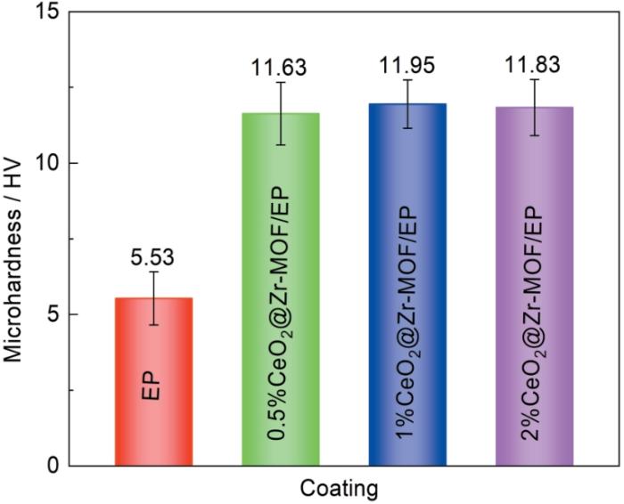
图10
加入不同比例CeO2@Zr-MOF后环氧树脂涂层的硬度
Fig.10
Hardness of epoxy coatings after adding different ratios of CeO2@Zr-MOF
2.3.2 复合涂层附着力测试
测定了0.5%、1%及2%CeO2@Zr-MOF作为填料加入涂层后涂层的附着强度并与EP作对比以评估复合涂层的附着强度,结果如图11所示。由图可知相比于纯环氧树脂涂层,加入0.5%、1%及2%CeO2@Zr-MOF后涂层附着力分别提升了16.93%、18.50%及14.96%,表明加入CeO2@Zr-MOF填料可显著增加环氧树脂涂层在基体材料上的附着力,增加了涂层抵抗外界环境侵蚀的能力。加入CeO2@Zr-MOF纳米填料后涂层附着力提升可归因于几个方面:首先CeO2@Zr-MOF材料的部分介孔结构增加了与环氧树脂的接触面积,从而增强了涂层的机械嵌扣;再有填料的加入填充了环氧树脂涂层内部的一些缺陷,使得涂层结构更为完整[19,20]。
图11
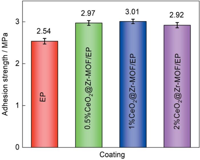
图11
不同比例CeO2@Zr-MOF环氧涂层在基材上的附着力
Fig.11
Adhesion strengths of CeO2@Zr-MOF epoxy coatings with different ratios on zinc-magnesium-aluminum steel substrate
2.3.3 复合涂层润湿性测试
测定比较了0.5%、1%及2%CeO2@Zr-MOF作为填料加入涂层后涂层的水接触角并与EP作对比以评估CeO2@Zr-MOF环氧涂层的润湿性,结果如图12所示。由图可知添加0.5%、1%及2%CeO2@Zr-MOF后涂层接触角分别为68.65°、69.91°及70.21°,较纯环氧树脂涂层接触角提升了12°~14°。加入CeO2@Zr-MOF材料后环氧树脂涂层的接触角得到了进一步的提高,具有更好的疏水性。
图12
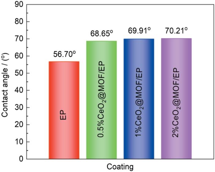
图12
不同比例CeO2@Zr-MOF环氧涂层的水接触角测试结果
Fig.12
Results of contact angle tests of epoxy coatings with different ratios of CeO2@Zr-MOF
2.4 CeO2@Zr-MOF复合涂层的防腐性能分析
为进一步评价CeO2@Zr-MOF环氧树脂涂层对ZMA钢基体的保护作用,对CeO2@Zr-MOF涂层进行EIS测试,结果如图13所示。Bode图低频(|Z|0.01 Hz)阻抗值是评估涂层保护能力的关键参数,与涂层的腐蚀防护性能密切相关。图13a2中纯环氧树脂涂层的|Z|0.01 Hz值从一开始的9.78 × 10⁹ Ω·cm2急剧下降到48 d后的7.83 × 10⁷ Ω·cm2,表明纯环氧树脂涂层在盐水侵蚀下快速失效,推测是由于涂层存在的孔隙和较差的屏蔽性能使盐溶液渗透到基体上,加速了腐蚀进程。图13b2可见添加0.5%CeO2@Zr-MOF环氧树脂涂层的环氧涂层的|Z|0.01 Hz值在浸泡60 d后较纯EP涂层提升2.7个数量级。图13d2中添加2%CeO2@ Zr-MOF的环氧涂层的|Z|0.01 Hz值较0.5%CeO2@ Zr-MOF的环氧涂层的|Z|0.01 Hz值下降0.7个数量级,推测是由于CeO2@Zr-MOF添加过多造成了一部分填料在环氧树脂内部团聚从而降低了环氧树脂的整体性。在图13c2中1%CeO2@Zr-MOF的环氧涂层表现出更高的|Z|0.01 Hz值,其在浸泡初期|Z|0.01 Hz值为10.88 × 10¹⁰ Ω·cm2,显著高于纯环氧树脂涂层的|Z|0.01 Hz值,并且在浸泡60 d之后其|Z|0.01 Hz值高于纯环氧树脂涂层3个数量级,表现出优异的腐蚀防护性能。添加CeO2@Zr-MOF后环氧树脂涂层防腐性能进一步提升,这归因于CeO2@Zr-MOF的添加填补了环氧树脂的孔隙和微裂纹,从而提升了涂层整体的完整性,同时CeO2@Zr-MOF均匀且致密的孔结构提升了涂层的致密性使涂层在长期处于侵蚀环境中时依旧对金属基体保持较好的腐蚀防护性能。
图13
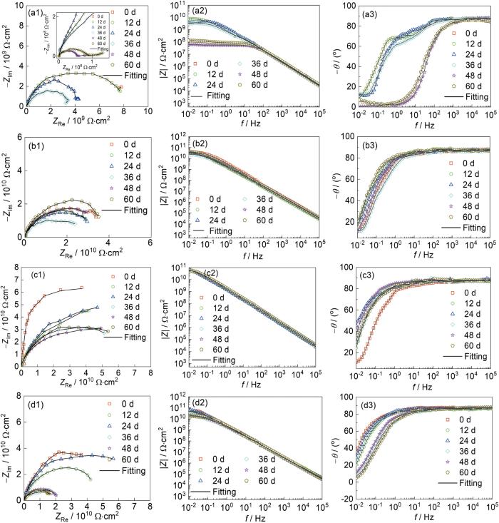
图13
不同添加量CeO2@Zr-MOF环氧涂层的EIS测试结果
Fig.13
EIS test results of CeO2@Zr-MOF epoxy coatings with different additions: (a1-a3) EP, (b1-b3) 0.5%CeO2@Zr-MOF/EP, (c1-c3) 1%CeO2@Zr-MOF/EP, (d1-d3) 2%CeO2@Zr-MOF/EP
为进一步判断涂层的防腐性能,利用相应的等效电路(图14)对所得到的电化学阻抗谱进行拟合,结果如表1所示。其中Rs,Rct和Rc分别代表整个体系的溶液电阻,电化学反应的电荷转移电阻和涂层自身的电阻,CPEc和CPEdl分别代表涂层和基体界面的恒相位元件以及电解液和涂层界面的恒相位元件。一般认为Rc值越高涂层耐蚀能力越强。从图15可见纯EP涂层的Rc和Rct值随着浸泡时间的增加整体呈下降趋势,而0.5%CeO2@Zr-MOF环氧涂层Rc随浸泡时间的增加整体呈增长趋势,2%CeO2@ Zr-MOF环氧涂层Rc随浸泡时间的增加呈现先增长后减少的趋势,表明了CeO2@Zr-MOF在涂层的腐蚀防护中发挥的作用。其中1%CeO2@Zr-MOF环氧涂层Rc随浸泡时间的增加呈现增长趋势且较为稳定,并且Cdl值进一步下降也证实了CeO2@Zr-MOF添加量为1%时环氧树脂涂层的腐蚀防护性能最佳。
图14
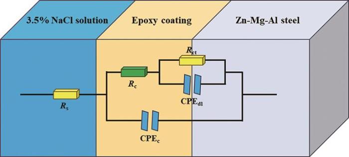
图14
CeO2@Zr-MOF环氧涂层的等效电路图
Fig.14
Equivalent circuit diagram for CeO2@Zr-MOF epoxy coating
表1 3.5%NaCl溶液中浸泡不同时间纯EP涂层以及不同添加量的CeO2@Zr-MOF/EP涂层在ZMA镀层钢板上的EIS拟合参数
Table 1
| Samples | Time / d | CPEc | Rc / Ω·cm2 | Cc / F·cm2 | CPEdl | Rct / Ω·cm2 | Cc / F·cm2 | ||
|---|---|---|---|---|---|---|---|---|---|
| Y1 / Ω-1·cm-2·s n | n1 | Y2 / Ω-1·cm-2·s n | n2 | ||||||
| EP | 0 | 7.00 × 10⁻¹¹ | 1 | 4.24 × 10⁸ | 7.00 × 10⁻¹¹ | 1.34 × 10⁻¹⁰ | 1 | 7.59 × 10⁹ | 1.34 × 10⁻¹⁰ |
| 12 | 8.99 × 10⁻¹¹ | 0.97 | 4.11 × 10⁸ | 8.12 × 10⁻¹¹ | 1.44 × 10⁻¹⁰ | 0.84 | 8.05 × 10⁹ | 1.48 × 10⁻¹⁰ | |
| 24 | 6.54 × 10⁻¹¹ | 0.98 | 4.61 × 10⁸ | 6.09 × 10⁻¹¹ | 8.37 × 10⁻¹¹ | 0.79 | 8.18 × 10⁸ | 8.36 × 10⁻¹¹ | |
| 36 | 7.08 × 10⁻¹¹ | 1 | 8.91 × 10⁷ | 7.08 × 10⁻¹¹ | 1.73 × 10⁻¹⁰ | 1 | 3.30 × 10⁸ | 1.73 × 10⁻¹⁰ | |
| 48 | 9.71 × 10⁻¹¹ | 0.95 | 3.35 × 10⁷ | 7.38 × 10⁻¹¹ | 2.45 × 10⁻⁷ | 0.78 | 8.14 × 10⁷ | 3.30 × 10⁻⁷ | |
| 60 | 7.83 × 10⁻¹¹ | 0.96 | 3.16 × 10⁷ | 6.49 × 10⁻¹¹ | 1.60 × 10⁻⁸ | 0.33 | 1.40 × 10⁷ | 3.63 × 10⁻⁸ | |
| 0.5%CeO2@Zr-MOF | 0 | 6.03 × 10⁻¹¹ | 1 | 1.94 × 10⁹ | 6.03 × 10⁻¹¹ | 3.89 × 10⁻¹⁰ | 0.77 | 3.03 × 10¹⁰ | 5.44 × 10⁻¹¹ |
| 12 | 6.69 × 10⁻¹¹ | 0.97 | 2.57 × 10⁹ | 6.34 × 10⁻¹¹ | 1.13 × 10⁻¹⁰ | 0.76 | 8.00 × 10¹⁰ | 1.11 × 10⁻¹⁰ | |
| 24 | 6.66 × 10⁻¹¹ | 0.97 | 3.86 × 10⁹ | 6.24 × 10⁻¹¹ | 3.92 × 10⁻¹⁰ | 0.53 | 9.06 × 10¹⁰ | 2.45 × 10⁻¹⁰ | |
| 36 | 6.52 × 10⁻¹¹ | 0.98 | 4.60 × 10⁹ | 6.31 × 10⁻¹¹ | 3.16 × 10⁻¹¹ | 0.74 | 1.68 × 10¹¹ | 3.63 × 10⁻¹¹ | |
| 48 | 4.87 × 10⁻¹¹ | 1 | 2.60 × 10⁹ | 4.87 × 10⁻¹¹ | 4.27 × 10⁻¹¹ | 0.74 | 1.60 × 10¹¹ | 5.47 × 10⁻¹¹ | |
| 60 | 4.69 × 10⁻¹¹ | 0.98 | 3.21 × 10⁹ | 4.72 × 10⁻¹¹ | 3.31 × 10⁻¹¹ | 1 | 3.94 × 10¹⁰ | 3.31 × 10⁻¹¹ | |
| 1%CeO2@Zr-MOF | 0 | 5.70 × 10⁻¹¹ | 1 | 4.49 × 10⁹ | 5.70 × 10⁻¹¹ | 1.47 × 10⁻¹¹ | 1 | 2.93 × 10¹⁰ | 1.47 × 10⁻¹¹ |
| 12 | 7.00 × 10⁻¹¹ | 1 | 6.73 × 10⁹ | 7.00 × 10⁻¹¹ | 7.61 × 10⁻¹¹ | 1 | 8.90 × 10¹⁰ | 7.61 × 10⁻¹¹ | |
| 24 | 5.01 × 10⁻¹¹ | 0.99 | 7.69 × 10⁹ | 4.98 × 10⁻¹¹ | 1.18 × 10⁻¹⁰ | 0.70 | 9.85 × 10¹⁰ | 1.19 × 10⁻¹⁰ | |
| 36 | 6.44 × 10⁻¹¹ | 0.97 | 6.27 × 10⁹ | 6.07 × 10⁻¹¹ | 2.47 × 10⁻¹¹ | 0.63 | 1.43 × 10¹¹ | 3.74 × 10⁻¹¹ | |
| 48 | 5.84 × 10⁻¹¹ | 1 | 2.39 × 10⁹ | 5.84 × 10⁻¹¹ | 3.58 × 10⁻¹¹ | 0.72 | 1.34 × 10¹¹ | 4.99 × 10⁻¹¹ | |
| 60 | 6.20 × 10⁻¹¹ | 0.98 | 6.11 × 10⁹ | 5.98 × 10⁻¹¹ | 2.70 × 10⁻¹¹ | 0.68 | 1.11 × 10¹¹ | 3.86 × 10⁻¹¹ | |
| 2%CeO2@Zr-MOF | 0 | 6.68 × 10⁻¹¹ | 0.97 | 4.34 × 10⁹ | 6.69 × 10⁻¹¹ | 2.54 × 10⁻¹¹ | 0.96 | 6.34 × 10¹⁰ | 2.58 × 10⁻¹¹ |
| 12 | 6.80 × 10⁻¹¹ | 0.97 | 5.74 × 10⁹ | 6.70 × 10⁻¹¹ | 2.46 × 10⁻¹¹ | 0.64 | 8.27 × 10¹⁰ | 1.10 × 10⁻¹¹ | |
| 24 | 4.90 × 10⁻¹¹ | 0.98 | 6.15 × 10⁹ | 4.75 × 10⁻¹¹ | 1.03 × 10⁻¹¹ | 0.85 | 1.04 × 10¹¹ | 1.10 × 10⁻¹¹ | |
| 36 | 6.75 × 10⁻¹¹ | 0.97 | 1.72 × 10⁹ | 6.38 × 10⁻¹¹ | 4.79 × 10⁻¹¹ | 0.67 | 2.11 × 10¹⁰ | 4.83 × 10⁻¹¹ | |
| 48 | 4.68 × 10⁻¹¹ | 1 | 4.54 × 10⁹ | 4.68 × 10⁻¹¹ | 1.81 × 10⁻¹¹ | 1 | 1.52 × 10¹⁰ | 1.81 × 10⁻¹¹ | |
| 60 | 9.64 × 10⁻¹¹ | 0.98 | 4.74 × 10⁹ | 9.52 × 10⁻¹¹ | 3.85 × 10⁻¹¹ | 0.80 | 1.87 × 10¹⁰ | 3.62 × 10⁻¹¹ | |
图15
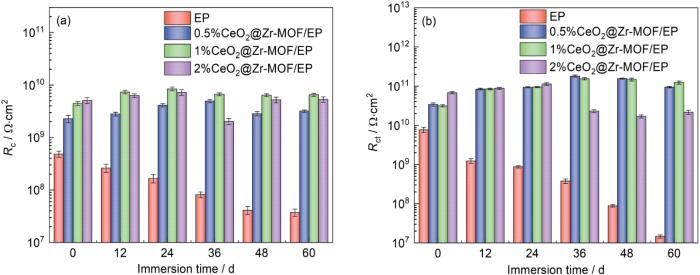
图15
不同添加量CeO2@Zr-MOF环氧涂层在不同浸泡时间下的Rc和Rct值
Fig.15
Rc (a) and Rct (b) values of CeO2@Zr-MOF epoxy coatings with different additions at different immersion times
2.5 CeO2@Zr-MOF复合涂层的中性盐雾实验分析
为进一步探究CeO2@Zr-MOF涂层的耐蚀性能,将CeO2@Zr-MOF不同添加量的环氧树脂涂层经过划伤处理后放置于盐雾试验箱中,经400 h后取出观察其表面形貌。盐雾试验前,样品表面的划痕尺寸大小一致,因此通过观察划痕破损的情况即可判断出涂层的腐蚀防护性能。实验结果如图16所示。由图可见,纯EP涂层样品在400 h后划痕处腐蚀较为严重,腐蚀介质渗透进涂层中导致金属基体腐蚀严重。而0.5%CeO2@Zr-MOF涂层划痕在400 h后出现了一定程度上的愈合,表明了CeO2@Zr-MOF涂层中CeO2的自修复作用。2%MOF涂层可以看出腐蚀程度极小。1%CeO2@Zr-MOF涂层可以看出几乎没有发生腐蚀,与电化学结果吻合。以上结果显示当CeO2@Zr-MOF的添加量为1%时,涂层的腐蚀防护性能最佳。
图16
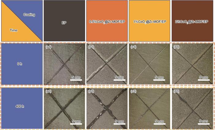
图16
400 h后不同比例CeO2@Zr-MOF划伤涂层的盐雾实验结果
Fig.16
Salt spray experimental results of Zr-MOF scratch coatings 0 h (a1-d1) and after 400 h (a2-d2): EP (a), 0.5% CeO2@Zr-MOF/EP (b), 1%CeO2@Zr-MOF/EP (c) and 2%CeO2@Zr-MOF/EP (d)
综上所述,CeO2@Zr-MOF的添加提升了环氧树脂涂层的腐蚀防护性能,而这种性能的显著提升归因于CeO2@Zr-MOF复合材料中MOF均匀发达的孔结构、较大的比表面积以及CeO2的高稳定性和自修复性。当CeO2@Zr-MOF添加量为1%时,涂层对基体的腐蚀防护性能最佳,这与电化学实验的结果吻合。
2.6 CeO2@Zr-MOF复合涂层的耐蚀机理分析
图17
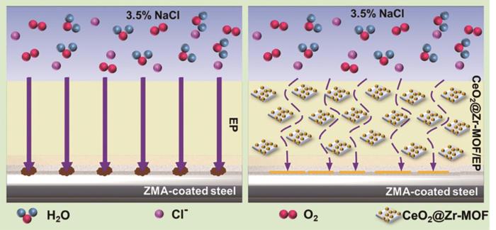
图17
CeO2@Zr-MOF涂层的腐蚀防护机制示意图
Fig.17
Schematic diagram of corrosion protection mechanism of CeO2@Zr-MOF coating
与纯环氧树脂涂层相比,添加CeO2@Zr-MOF纳米填料涂层的腐蚀防护性能有了明显的提升,耐蚀机理如图17所示。首先CeO2@Zr-MOF具有部分均匀的介孔结构,CeO2@Zr-MOF的加入提升了涂层的致密性,为金属基体提供了更有力的保护。其次CeO2@Zr-MOF均匀的介孔结构可以通过毛细作用吸附渗透溶液,从而延缓腐蚀介质的侵袭。另外Zr-MOF在高碱性和低酸性条件下部分溶解导致Zr阳离子和有机化合物的释放。释放的Zr离子和有机化合物分别与金属表面生成的OH-和Fe2+反应,覆盖在腐蚀的阴极和阳极区域[22~24],从而对金属基体起到更好的腐蚀防护作用。最后CeO2@Zr-MOF中的CeO2具有较高的比表面积,这加速了铈离子的产生和释放,而铈离子是一种环保的沉淀膜型缓蚀剂,可以在钢表面形成沉淀膜以更好地保护金属基体。
3 结论
(1) SEM、TEM、XRD、BET、XPS和FTIR结果证明了CeO2在MOF表面的成功负载,表明CeO2@Zr-MOF的成功合成。
(2) 将CeO2@Zr-MOF作为填料加入环氧树脂涂层中,可使复合涂层的硬度、附着力和接触角均有很大程度上的提升。
(3) 添加CeO2@Zr-MOF的环氧树脂涂层耐蚀性能明显优于Zr-MOF环氧树脂涂层和纯环氧树脂涂层,其中1%CeO2@Zr-MOF环氧树脂涂层的耐蚀性能最佳,在浸泡60 d后其在0.01 Hz处的阻抗模量值始终保持在较高的数值,高于纯环氧树脂涂层3个数量级,表现出最佳的腐蚀防护性能,为锌镁铝镀层钢板提供更好的保护效果。
参考文献
Corrosion inhibition performance of biomass-derived carbon dots on Q235 steel
[J].
生物质碳点对Q235钢的缓蚀性能研究
[J].
金属腐蚀威胁金属设施的安全性和可靠性,也加剧了环境污染和经济损失问题。然而,使用可持续、可再生且经济的原材料制备绿色缓蚀剂现阶段仍是有挑战性难题。本文以荔枝叶为原料制备了生物质基碳点(CDs),并采用失重法、电化学阻抗谱和动电位极化曲线系统研究了其在1 mol/L HCl中对Q235钢的缓蚀性能。所获得的生物质基CDs具有丰富的含氧和含氮官能团,这些官能团使CDs在1 mol/L HCl溶液中保持稳定,具有长期有效的缓蚀性能。
Fluorescent nanofiller modified epoxy coatings for visualization of coating degradation
[J].
采用荧光纳米填料改性环氧涂层实现缺陷可视化
[J].通过水热法制备了8-羟基喹啉锌 (ZnQ<sub>2</sub>) 荧光耐蚀双功能纳米填料,并添加到环氧树脂中制备荧光指示底漆;以单宁酸修饰的碳纳米管 (TA-CNTs) 作为填料制备高阻隔性环氧面漆,最终合成具有荧光缺陷指示与高耐蚀的双功能涂层。利用SEM、FT-IR、XRD、荧光光谱等验证了荧光纳米材料的成功合成;通过电化学测试和盐雾实验对该复合涂层的耐蚀性进行了评价,并通过荧光显微镜对复合改性涂层的缺陷指示功能进行了验证。结果表明:合成的ZnQ<sub>2</sub>纳米填料具有优异的荧光指示和缓蚀作用,复合涂层经30 d的中性盐雾实验后,其低频阻抗|Z|<sub>0.01 Hz</sub>仍保持在2.95×10<sup>9</sup> Ω·cm<sup>2</sup>,表现出了优异的耐蚀性。当复合涂层发生机械损伤时,涂层破损处在365 nm紫外照射下可发生强烈荧光。且经过盐雾实验10 d后,涂层缺陷处的荧光依旧保持良好,表明该荧光涂层有利于对涂层缺陷的快速诊断和维修指示。
Development of metal-organic framework (MOF) decorated graphene oxide/MgAl-layered double hydroxide coating via microstructural optimization for anti-corrosion micro-arc oxidation coatings of magnesium alloy
[J].An efficient and simple in-situ growth strategy has been discovered for the preparation of highly reproducible and continuous symbiotic ZIF-8-based anticorrosion coating by using graphene oxide (GO)/MgAl-NO3 layered double hydroxides (G/LDHs) buffer layer as a new type of connecting carrier based on micro-arc oxide (MAO) coating of AZ31 magnesium alloy. The components of ZIF-8 were adsorbed and bounded to the surface of the G/LDHs buffer layer-modified substrates to promote the nucleation of ZIF-8, thus growing a phase-pure, uniform, and good symbiosis ZIF-8 membrane. ZIF-8 particles with different growth times compensate for the grain boundary defects of the G/LDHs coating precursor buffer layer to different degrees. The prepared ZIF-8-based coating has excellent stability and corrosion resistance. The results demonstrate that the G/LDHs buffer layer provides a new channel for the MOF-modified MAO substrate of AZ31 magnesium alloy. It also proves that it is feasible to build high-performance anticorrosive coatings with MOF materials.
Electrochemical performance of metal-organic framework MOF(Ni) doped graphene
[J].
Research progress of nanofillers for epoxy anti-corrosion coatings
[J].
纳米填料在环氧防腐涂层中的应用研究进展
[J].
Functional porous coordination polymers
[J].
Selective binding and removal of guests in a microporous metal-organic framework
[J].
Hierarchical Zn/Ni-MOF-2 nanosheet-assembled hollow nanocubes for multicomponent catalytic reactions
[J].
Hydrogen adsorption in metal-organic frameworks: Cu-MOFs and Zn-MOFs compared
[J].
Preparation of a BTA-UIO-GO nanocomposite to endow coating systems with active inhibition and passive anticorrosion performances
[J].
Preparation and perfromance of rare earth cerium modified graphene oxide/waterborne epoxy resin composite coating
[J].
稀土铈改性石墨烯/水性环氧树脂复合涂料涂装技术研究
[J].
Preparation and performance of CeO2@MWCNTs/EP composite coatings
[J].
CeO2@MWCNTs/EP复合涂层的制备与性能研究
[J].在X80钢上制备了CeO<sub>2</sub>@MWCNTs改性的环氧复合涂层 (CeO<sub>2</sub>@MWCNTs/EP),研究了复合涂层的腐蚀行为和摩擦学性能。利用扫描电子显微镜(SEM)、透射电子显微镜 (TEM) 和白光干涉仪对其形貌进行表征,利用能谱仪 (EDS)、X射线光电子能谱仪 (XPS)、红外光谱 (FT-IR) 等分析其化学成分和结构,采用接触角计和显微维氏硬度计分别对复合涂层的润湿性和硬度进行测试。结果显示,CeO<sub>2</sub>与MWCNTs之间发生物理吸附,纳米CeO<sub>2</sub>可以改变EP的结构;CeO<sub>2</sub>@MWCNTs有利于减少CeO<sub>2</sub>@MWCNTs/EP复合涂层中的微孔,而当CeO<sub>2</sub>@MWCNTs含量达到1.0%时,则发生团聚;CeO<sub>2</sub>@MWCNTs不发生团聚时,可以提高复合涂层的耐蚀性,否则效果相反;随着CeO<sub>2</sub>@MWCNTs含量增加,复合涂层的耐蚀性先提高后降低,当CeO<sub>2</sub>@MWCNTs含量为0.5%时,复合涂层的腐蚀电流密度最小,与EP涂层相比降低了一个数量级;CeO<sub>2</sub>@MWCNTs具有润滑功能,随着CeO<sub>2</sub>@MWCNTs含量的增加,复合涂层的摩擦系数和磨损率呈下降趋势,1.0% CeO<sub>2</sub>@MWCNTs/EP复合涂层的磨损率比EP涂层下降了64.7%。
Effect of Nano-CeO2 on anticorrosion performance for polyurethane coating
[J].
添加纳米CeO2对聚氨酯涂层防腐性能的影响
[J].采用盐雾和盐水浸泡加速实验,结合ATR-FTIR,SEM,AFM表面分析技术及EIS电化学分析技术,考察纳米CeO<sub>2</sub>作为涂层颜料对聚氨酯涂层防腐性能的影响。结果表明,添加纳米CeO<sub>2</sub>能改善涂层的防腐性能,延缓聚氨酯涂层的阻抗衰减进程,但同时会削弱涂层在金属基体上的附着力。当添加量较低时 (≤0.5%,质量分数),由于H<sub>2</sub>O和侵蚀性离子渗入聚氨酯层,纳米CeO<sub>2</sub>水解流失,导致涂层阻抗谱随时间降低较快;当添加量达到1.0%时,涂层阻抗在较长时间内保持较高值,这可能是由于纳米CeO<sub>2</sub>在涂层微孔中发生水解膨胀,压缩了孔隙通道,同时Ce (III,IV) 迁移到铝合金/涂层界面,抑制了腐蚀活性位点,因而减缓了阻抗的衰减进程。然而,在盐雾实验后期,CeO<sub>2</sub>进一步水解会导致Ce<sup>4+</sup>的溶解流失,造成微孔隙的再次疏通和涂层阻抗的快速下降。过量添加 (>1.0%) 还会削弱涂层在铝合金基体上的附着力。长期浸泡实验结果表明:添加1.0%CeO<sub>2</sub>可基本实现Ce<sup>4+</sup>溶解和流失的平衡,增强聚氨酯涂层的防腐性能。
In-situ-construction of BiOI/UiO-66 heterostructure via nanoplate-on-octahedron: a novel p-n heterojunction photocatalyst for efficient sulfadiazine elimination
[J].
2D nanomaterials reinforced organic coatings for marine corrosion protection: state of the art, challenges, and future prospectives
[J].
Robust Cr(VI) reduction over hydroxyl modified UiO-66 photocatalyst constructed from mixed ligands: performances and mechanism insight with or without tartaric acid
[J].
Development of an active/barrier bi-functional anti-corrosion system based on the epoxy nanocomposite loaded with highly-coordinated functionalized zirconium-based nanoporous metal-organic framework (Zr-MOF)
[J].
Zr-based metal-organic frameworks: design, synthesis, structure, and applications
[J].Among the large family of metal-organic frameworks (MOFs), Zr-based MOFs, which exhibit rich structure types, outstanding stability, intriguing properties and functions, are foreseen as one of the most promising MOF materials for practical applications. Although this specific type of MOF is still in its early stage of development, significant progress has been made in recent years. Herein, advances in Zr-MOFs since 2008 are summarized and reviewed from three aspects: design and synthesis, structure, and applications. Four synthesis strategies implemented in building and/or modifying Zr-MOFs as well as their scale-up preparation under green and industrially feasible conditions are illustrated first. Zr-MOFs with various structural types are then classified and discussed in terms of different Zr-based secondary building units and organic ligands. Finally, applications of Zr-MOFs in catalysis, molecule adsorption and separation, drug delivery, and fluorescence sensing, and as porous carriers are highlighted. Such a review based on a specific type of MOF is expected to provide guidance for the in-depth investigation of MOFs towards practical applications.
Intelligent anticorrosion coating based on mesostructured BTA@mCeO2/g-C3N4 nanocomposites for inhibiting the filiform corrosion of Zn-Mg-Al coated steel
[J].
Sustainable Corrosion Inhibitors II: Synthesis, Design, and Practical Applications
[M].
Effect of the microstructure of Zn-Al and Zn-Al-Mg model alloys on corrosion stability
[J].
Development of metal-organic framework (MOF) decorated graphene oxide nanoplatforms for anti-corrosion epoxy coatings
[J].
A stable metal-organic framework featuring a local buffer environment for carbon dioxide fixation
[J].
Zirconium metal-organic framework UiO-66: stability in an aqueous environment and its relevance for organophosphate degradation
[J].Zirconium-based metal-organic frameworks were recently investigated as catalysts for degradation of organophosphate toxic compounds, such as pesticides or chemical warfare agents. The most utilized UiO-66 is considered as a stable material for these applications in an aqueous environment. However, the presented results indicate that the properties of UiO-66 are changing considerably in aqueous media under common conditions used for organophosphate degradations, and therefore its catalytic activity is not related to the number of structural defects created during the material synthesis. We delineate the stability of UiO-66 in water of various pHs, the in situ formation of new catalytic sites, and the correlation of these two parameters with the degradation rate of a model organophosphate pollutant, dimethyl-4-nitrophenyl phosphate (methyl-paraoxon). The stability was quantified using high-performance liquid chromatography (HPLC) by measuring the amounts of leached terephthalic acid, the linker of UiO-66, and monocarboxylic acids, the modulators bound at UiO-66 defects. We demonstrate that the HPLC analysis is a more suitable method for metal-organic frameworks stability assessment than commonly used methods, e.g., powder X-ray diffraction, adsorption isotherms, or electron microscopy.
