


ASTM国际G40-13标准认为冲蚀是由于固体表面与流体、多组分流体、撞击液体或撞击固体颗粒之间的机械相互作用而导致原始材料从固体表面逐渐流失的现象。研究表明,一个工业化国家的冲蚀磨损成本约占其国民生产总值的1%至4%[1]。冲蚀经常发生在采矿、冶金、石油、天然气等工业生产中,特别是泵、旋风分离器、燃气轮机叶片、气力输送管道等部件中[2~5],其中气力输送管道中的冲蚀破坏更为严重[6]。气力输送管道主要由水平管、垂直管和弯管组成。弯管作为改变流动方向的部件,起着连接水平管和垂直管的作用,更容易发生冲蚀。研究表明,弯管冲蚀破坏的程度约为直管段的50倍[7]。这种冲蚀破坏不仅浪费材料,消耗能源,降低设备效率,而且加速设备故障,降低弯管的使用寿命,对管路系统的安全运行造成威胁,从而酿成更大的经济损失。目前常用计算流体力学-离散相方法 (CFD-DPM) 和计算流体力学-离散元方法 (CFD-DEM) 方法研究冲蚀。CFD-DPM仅适用于稀相流,而CFD-DEM方法在计算密相流方向有更大的优势。合理的弯头结构以提高弯管的抗冲蚀性能在工业生产中具有重要意义,研究者对弯管结构进行了大量改进以提高弯管的抗冲蚀性能。Duarte等[8]提出一种沿水流方向扭转管壁的新颖管壁设计,这种结构会在弯头上游产生一个旋流,最大冲蚀率减小33%。San等[9]提出一种涡流室设计,并分析流动Reynold数、颗粒Stokes数和涡流室大小对冲蚀的影响,结果表明:与普通半径的弯管相比,涡流室总能减少侵蚀。以上改变弯管结构的方法虽能一定程度上减少冲蚀,但改变了弯管原本结构,影响了管道整体布局,且冲蚀仍发生在弯管壁面上,发生冲蚀破坏时候仍需替换弯管[10]。相比以上直接改变弯管结构的方法,内壁面增加肋条是更直接有效的方法,冲蚀破坏中只有肋条需被更换[11]。Yao等[12]通过实验方法分析弯管加横截面为四边形肋条的抗冲蚀性能,结果表明:肋条可提高弯管的抗冲蚀性能,矩形肋条相比方形肋条抗冲蚀性能更佳。Fan等[13]研究了横截面为矩形、等腰三角形、等腰直角三角形3种不同截面形状肋条的抗冲蚀性能,结果表明:3种不同形状肋均提高弯管的抗冲蚀性能,等腰直角三角形肋条的抗冲蚀能力最强。以上均在横截面为正方形弯管中均匀分布多个肋条,未见圆形弯管且未考虑单个肋在弯管不同角度的抗冲蚀分布。再者,Zhu等[14]虽将单个轴向角为5°,环形角为180°的肋条安装在90°圆形弯头外径方向不同位置上,但未考虑肋条横截面不同形状截面参数及多个肋条下的抗冲蚀特性。
为此,本文采用CFD-DPM方法,研究气力输送弯管中具有四边形、等腰梯形、等腰三角形3种横截面形状肋条的抗冲蚀特性,讨论肋条不同位置、形状、尺寸、数量下的冲蚀规律,扩展肋条结构在弯管抗冲蚀设计中的应用。其结论可直接应用于弯管的抗冲蚀优化设计。
1 理论模型
1.1 连续相模型
其中,ρ表示气体连续相密度,kg/m3;v是流体速率,m/s;p为压力,Pa;g是重力加速度,m/s2;μ为气体粘度,Pa·s;Smom是附加源项。
式中,Gk和Gb分别表示由平均速度梯度和升力引起的湍动能产生项;σk和σε 分别为湍动能k和湍动耗散率ε对应的Prandtl数;
1.2 离散相模型
图1
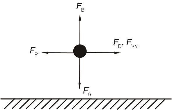
式中,FD和FB分别为颗粒所受的流体曳力和升力,FP为连续相流场压力梯度对颗粒产生的压力梯度力,FVM为颗粒表观质量效应产生的虚拟质量力,N;ρp为颗粒密度,kg/m3;dp为颗粒的直径,m;vp为颗粒速度,m/s;Rep为颗粒Reynolds数,定义为:
1.3 冲蚀模型与壁面碰撞方程
式中,C=2.17×10⁻⁷为经验常数;BH为靶材的布氏硬度;FS为颗粒形状系数,球形为0.2;n为经验常数,取值2.41;Af为受冲蚀区域面积,m2;θ为侵入角,rad;f(θ)为侵入角函数。
粒子与壁面碰撞会发生能量传递与损失,这里采用法向恢复系数en和切向恢复系数et表示[22]:
2 具有肋条的弯管模型
2.1 具有肋条的弯管几何模型
图2

图2
具有肋条的弯管几何结构
Fig.2
Elbow geometry with rib of three different cross sections (a) and multiple rib (b)
2.2 网格划分及流场条件
图3
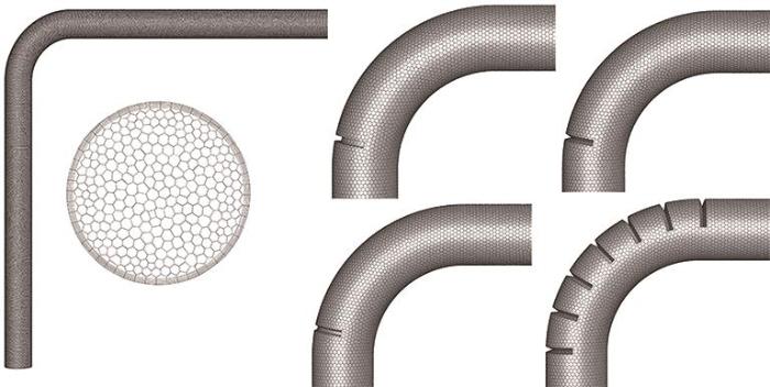
图4

气力输送中气固两相采用基于Euler-Lagrange方法的DPM模型。连续相为空气,密度1.18 kg/m3,粘度1.8×10-5 Pa·s;离散相为沙粒,密度1650 kg/m3,粒径为单一粒径100 μm,颗粒质量流量为0.02 kg/s。考虑连续相和颗粒相的双向耦合作用。边界条件设置中,连续相入口为速度入口,流速30 m/s,出口为大气压压力出口,壁面采用无滑移边界条件,近壁面处采用Launder和Spalding[23]提出的标准壁面函数;离散相为惰性颗粒垂直入口表面射入,入口出口边界条件为escape逃逸类型,壁面为reflect反射类型,假设入口处颗粒速率与连续相入口速率相同。
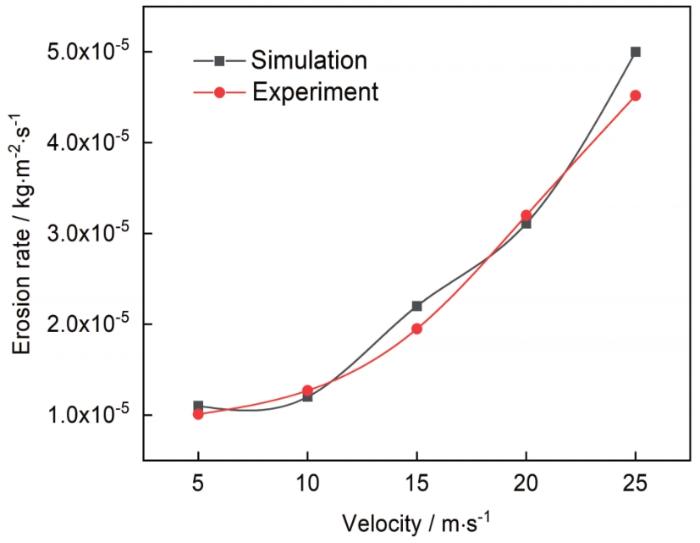
2.3 模型有效性验证
图5
3 结果与讨论
3.1 不同肋条形状对冲蚀的影响
图6
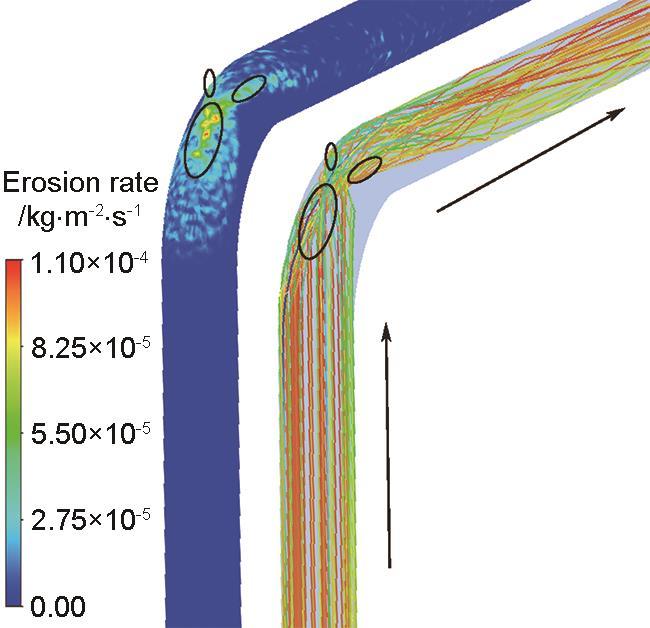
图6
普通弯管冲蚀分布及对应颗粒轨迹
Fig.6
Erosion distribution and particle trajectory of ordinary elbow
图7分别为3种截面形状的肋条安装在弯头不同角度θ下的最大冲蚀率变化,红色点线代表普通弯管的最大冲蚀率。由图7a可知,当肋条截面形状为四边形时,肋条部分的最大冲蚀率始终低于弯管部分,随弯管趋势变化。肋条位于θ=35°之前时,均具有不同程度的抗冲蚀效果,特别是θ=15°时,弯管的最大冲蚀率为6.89×10⁻⁵ kg/(m2·s),相比普通弯管减小37.36%;肋条安装在θ=35°~60°时,正处于普通弯管冲蚀严重区,肋条的安装反而加大了冲蚀;θ大于60°时,颗粒逐渐流出弯管,肋条的作用逐渐削弱,不具有明显的抗冲蚀性能。由图7b可知,当肋条截面形状为等腰梯形时,肋条部分的最大冲蚀率在θ=15°~35°出现高于弯管部分的现象,因单个肋条厚度较大,便于更换,充分发挥了肋条牺牲自身保护管壁的作用,具有较好的抗冲蚀效果。肋条位于θ=40°之前时,均具有不同程度的抗冲蚀效果,特别是θ=25°时,弯管部分最大冲蚀率为6.9×10-5 kg/(m2·s),相比普通弯管最大冲蚀率减小37.27%;其他角度下的最大冲蚀率变化趋势与四边形肋条结构的弯管相同。由图7c可知,当肋条截面形状为等腰三角形时,肋条部分的最大冲蚀率同样在θ=15°~35°出现高于弯管部分的现象,肋条部分保护壁面免受更大冲蚀,充分发挥了其牺牲作用。肋条位于θ=35°的之前时,均具有一定程度的抗冲蚀效果,特别是θ=20°,弯管的最大冲蚀率为6.63×10-5 kg/(m2·s),相比普通弯管最大冲蚀率减小39.72%。之后角度最大冲蚀率变化规律与四边形肋、梯形肋变化相同。总之,3种形状肋条安装在θ=35°前均具有一定的抗冲蚀效果,综合考虑肋条作用和抗冲蚀效果,等腰三角形肋条抗冲蚀作用最佳,且肋条起到牺牲自己保护壁面的作用;四边形肋和等腰梯形肋抗冲蚀作用相近,但等腰梯形肋充分发挥本身作用,四边形肋与弯管变化趋势相同,不便于冲蚀后肋条的替换安装。
图7
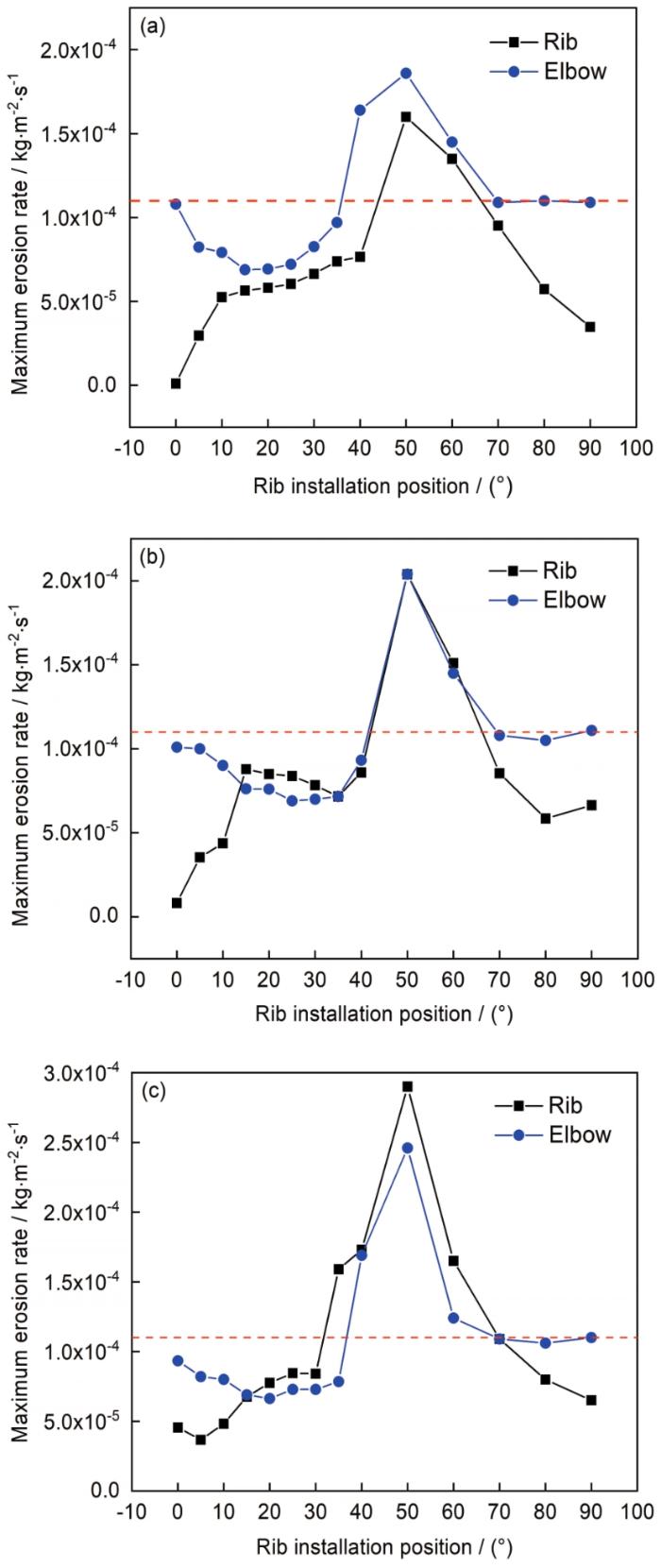
图7
不同形状肋条在弯头不同角度下的最大冲蚀率
Fig.7
Maximum erosion rate of rib at different elbow angles with different shapes of quadrilateral rib (a), isosceles trapezoidal rib (b) and isosceles triangular rib (c)
因颗粒轨迹对冲蚀形状的形成有重要影响,现根据普通弯管中颗粒与壁面的碰撞角度,选取θ=0°、20°、50°、70° 4个角度不同形状肋条的冲蚀进行分析。图8为横截面不同形状肋条在不同角度θ下的冲蚀率分布。从横向看,不同横截面形状肋条在相同位置下的冲蚀形状相似。从纵向看,肋条的加入改变了原本的冲蚀分布形状。当θ为0°、20°时,具有一定的抗冲蚀性能,冲蚀率较低。当θ较大时,在肋条处和肋条前冲蚀较为严重,最大冲蚀率大于普通弯管,不具有抗冲蚀性能。随着角度的增加,颗粒逐渐流出弯头区域,肋条发挥作用减弱。
图8
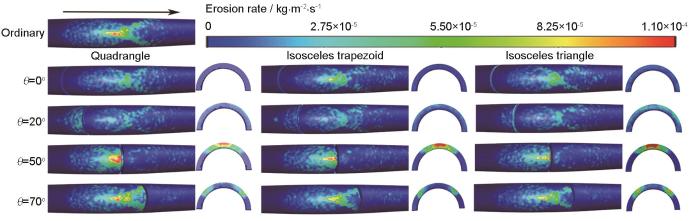
图8
不同形状肋条在不同角度θ下的冲蚀率分布
Fig.8
Erosion rate distribution of rib with different shapes at different angles θ
图9为不同形状肋条在不同角度下的颗粒轨迹图和速度矢量图。结合图7可知肋条改变了颗粒的运动轨迹。当安装在颗粒与壁面第一次碰撞35°之前时,大部分颗粒首先与肋条碰撞后反弹回管道,阻止了大部分颗粒对壁面的的第一次直接碰撞。θ处于35°~60°时,大部分颗粒已与壁面发生碰撞,在肋条处再次与肋条碰撞造成肋条前和肋条处颗粒堆积,造成冲蚀率增大。θ大于60°时,颗粒已完成与壁面第一次碰撞并分成两股相反对称的颗粒流直至与壁面再次碰撞,逐渐流出弯头区域,肋条发挥作用较小,抗冲蚀作用较弱。同时肋条的加入改变了近壁面处的流场分布,均在肋条背部形成一个低速逆流循环区,保护该区域免受直接冲蚀。当安装在20°附近时,不仅抑制了颗粒与壁面的第一次直接碰撞,而且正好保护了冲蚀最严重的区域,所以是最优抗冲蚀位置。从横向看,不同形状下的颗粒轨迹略有不同,可由图10所示颗粒在3种不同横截面形状下的弹性碰撞说明其差异性。当颗粒以相同的角度和3种截面形状肋条碰撞后颗粒方向不同,与四边形肋碰撞后垂直返回计算域,等腰梯形肋的实际碰撞角度为74°,等腰三角形肋为57°。
图9
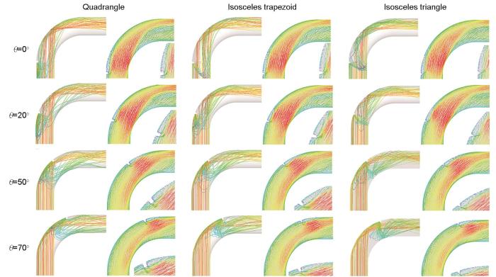
图9
不同形状肋条在不同角度θ下的颗粒轨迹和速度矢量图
Fig.9
Particle trajectory and velocity vectors of ribs with different shapes at different angles θ
图10
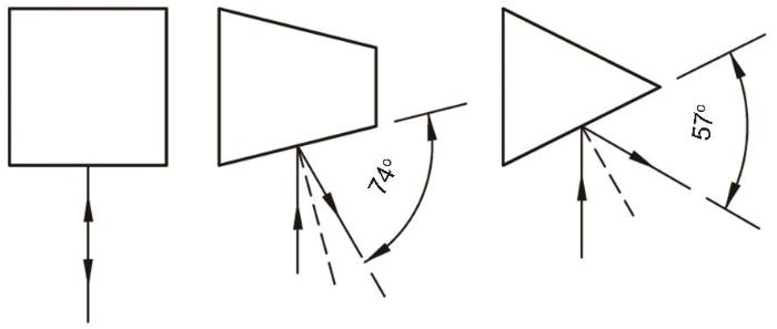
图10
颗粒在不同横截面形状下的碰撞示意图
Fig.10
Collision diagram of particles under different cross section shapes
3.2 不同肋条尺寸对冲蚀的影响
基于参考文献[10]中深度对循环区大小的形成有重要影响,现以肋条宽度L=5 mm为固定尺寸,分析不同肋高条件下的冲蚀变化。因四边形肋跟随弯管最大冲蚀变化,未充分发挥肋条作用,现仅讨论等腰梯形肋和等腰三角形肋。肋条安装在颗粒与壁面第一碰撞之前有更好的抗冲蚀性能,故研究10°、15°、20°、25°、30° 5个典型角度下肋条尺寸变化对冲蚀的影响。
图11为等腰梯形肋安装在10°、15°、20°、25°、30° 5种角度下尺寸变化对冲蚀的影响。随着肋条深度的增加,弯管和肋条部分的最大冲蚀率变化规律不明显,但总体呈现出肋条部分随H的增大波动增大,弯管部分在H<6 mm时,最大冲蚀率随肋条深度H的增加波动减小,H>6 mm时,弯管最大冲蚀率增加。图12为等腰三角形肋安装在10°、15°、20°、25°、30° 5种角度下尺寸变化对冲蚀的影响。肋条的变化始终跟随弯管的变化趋势。当θ为10°、15°、20°时,弯管和肋条的最大冲蚀率均随肋条深度H的增加而减小;当θ为25°、30°时,与等腰梯形肋变化趋势相同,弯管和肋条部分H<6 mm时,最大冲蚀率随肋深的增加减小,H>6 mm时,弯管随之增加。
图11
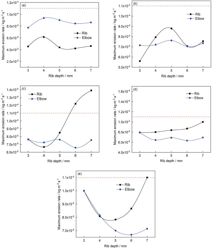
图11
等腰梯形肋在不同位置最大冲蚀率随深度的变化
Fig.11
Variation of the maximum erosion rate of isosceles trapezoidal ribs with depth at different positions of θ=10° (a), θ=15° (b), θ=20° (c), θ=25° (d) and θ=30° (e)
图12
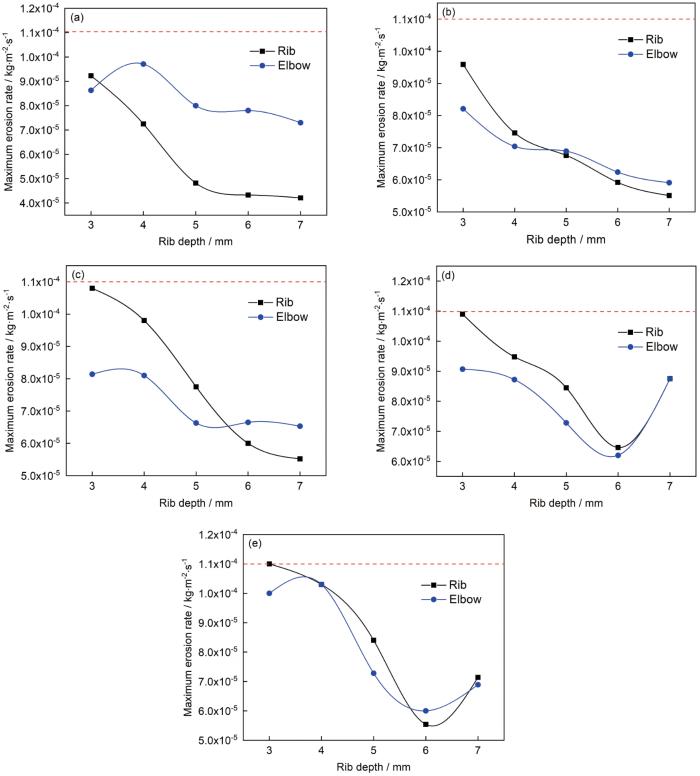
图12
等腰三角形肋在不同位置最大冲蚀率随深度的变化
Fig.12
Variation of the maximum erosion rate of isosceles triangular ribs with depth at different positions of θ=10° (a), θ=15° (b), θ=20° (c), θ=25° (d) and θ=30° (e)
图13
3.3 不同肋条数量对冲蚀的影响
以上一节中最佳抗冲蚀形状尺寸的肋条结构为固定条件,分析弯头部分均匀分布不同数量肋条对弯管冲蚀的影响。当肋条数为2时,肋条分布于弯管入口处和出口处,随着颗粒逐渐流出弯管,出口处肋条作用逐渐削弱,仅入口处肋条改变颗粒轨迹,与单肋条在入口处情况相似,弯管部分的冲蚀大于肋条部分的冲蚀,未充分发挥肋条自身作用,故仅从肋条数为3开始分析。图14为最大冲蚀率随肋条数量的变化。由图可知,肋条部分最大冲蚀率始终大于弯管部分,跟随弯管趋势变化,所考虑数量下随肋条数量的增加呈现“M”形变化趋势,抗冲蚀作用最佳的肋条数为7条,相比普通弯管抗冲蚀性能提高36.45%。图15为不同肋条数量下的速度矢量,肋条数量的增大减小了每个旋涡的大小,但增加了旋涡数量,对壁面起到一定的保护作用,但肋条数量增加影响了颗粒碰撞角度,增加颗粒与壁面碰撞频率,从而导致颗粒轨迹变化,冲蚀率发生变化。
图14
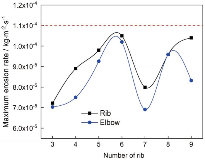
图15
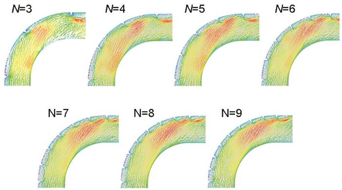
图15
不同数量下肋条的速度矢量图
Fig.15
Velocity vector diagram of ribs in different quan-tities
4 结论
(1) 肋条位于35°之前时,改变了颗粒轨迹,阻止了颗粒与壁面的第一次直接碰撞,一定程度上抑制了冲蚀,并且肋条背部形成一个低速逆流循环区,对该区域壁面产生一定保护作用。
(2) 四边形肋最大冲蚀率始终小于弯管部分,跟随弯管趋势变化;等腰梯形肋和等腰三角形肋位于θ=15-35°时具有牺牲自身保护壁面作用。综合考虑肋条的牺牲作用及抗冲蚀性能,等腰三角形肋抗冲蚀作用最佳。
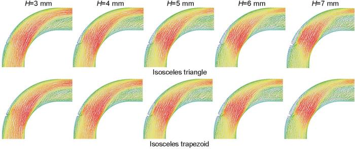
(3) 肋深越大,背部形成的循环区域越大,保护范围越大,但深度变化影响颗粒碰撞角度,增大颗粒与其碰撞频率,所以肋深并非越大越好。本文条件下肋深为6 mm的等腰三角形肋位于θ=25°抗冲蚀性能最佳,相比普通弯管抗冲蚀性能提高43.63%。
(4) 弯头部分均匀分布多个肋条也具有明显的抗冲蚀特性。肋条部分最大冲蚀率始终大于弯管,跟随弯管变化趋势,所考虑数量下随肋条数量的增加呈现“M”形趋势变化,肋条数为7的等腰三角形肋抗冲蚀性能最好。
参考文献
Fundamentals of wear failures
[A]. BeckerW T, ShipleyR J, eds. Failure Analysis and Prevention [M].
Numerical simulation prediction of erosion characteristics in a double-suction centrifugal pump
[J].
The double-suction centrifugal pumps installed along the Yellow River in China face serious sediment erosion due to the high sediment content which causes the poor operation efficiency of the pump units. The particle motion characteristics and erosion characteristics in a pump under different flow rates and different particle concentrations were numerically simulated based on the particle track model of solid-liquid two-phase flow. The results show that the flow rate has a significant effect on the particle tracks and the erosion caused by the particles in the impeller. The total erosion rate is positively correlated with the flow rate, and increases with the increase in flow rate. The vortex and secondary flow in the impeller have obvious influence on the particle trajectory, which increases the particle concentration at the trailing edge of the pressure surface and intensifies the impact erosion in this area. The particles carried by the vortex intensifies the local erosion. The particle concentration mainly affects the erosion rate, but has little effect on the erosion position. The influence of flow rate on pump erosion is greater than that of the particle properties. These results provide a reference for optimization of the design of anti-erosion blades of double-suction pumps and the regulation and operation of pumping stations.
Impact of non-uniform surface roughness on the erosion rate and performance of a cyclone separator
[J].
Effects of particle shape and swirling intensity on elbow erosion in dilute-phase pneumatic conveying
[J].
Influence of particle attrition on erosive wear of bends in dilute phase pneumatic conveying
[J].
Reducing bend erosion with a twisted tape insert
[J].
Effect of the gas-solid two-phase flow velocity on elbow erosion
[J].
Innovative pipe wall design to mitigate elbow erosion: A CFD analysis
[J].
Numerical study on erosion of a pipe bend with a vortex chamber
[J].
Design optimization of hemispherical protrusion for mitigating elbow erosion via CFD-DPM
[J].
Antierosion in a 90° bend by particle impaction
[J].
An experimental investigation of a new method for protecting bends from erosion in gas-particle flows
[J].
Large eddy simulation of the anti-erosion characteristics of the ribbed-bend in gas-solid flows
[J].In order to find out the ribs with the best anti-erosion efficiency, the erosion effects in three 90° duct bend gas-solid flows with different ribs are investigated and compared with that in the bare bend. Three different kinds of ribs are studied, which have square cross section, isosceles right-angled triangle shape cross section and isosceles triangle shape cross section, respectively. The arrangement and the geometry dimensions of the ribs are the same. The gas phase flow field is solved by the large eddy simulation technique considering the interaction between the gas and the particles, whereas the particles are tracked by Lagrangian method. The results exhibit that the erosion rates of all the ribbed bends are greatly reduced due to the adding of the ribs compared with that of the bare bend. Among the three different kinds of ribs, the isosceles right-angled triangle ribs have the highest anti-erosion ability. The reason is that the particle impact velocity on the walls in the isosceles right-angled triangle ribbed bends is decreased to the utmost and the corresponding particle impact angle is altered adequately due to the special shape of the ribs. In addition, the rib erosion rate, the sidewall erosion rate and the bend wall erosion rate are calculated separately. It is found that the rib erosion rate is half of the wall erosion rate, and the sidewall erosion rate is so low that it can be omitted compared with the bend wall erosion rate.
Numerical analysis of mitigating elbow erosion with a rib
[J].
Erosion of natural gas elbows due to rotating particles in turbulent gas-solid flow
[J].
Numerical simulation of air-solid erosion in elbow with novel arc-shaped diversion erosion-inhibiting plate structure
[J].
Experiment and simulation analysis of the suspension behavior of large (5-30 mm) nonspherical particles in vertical pneumatic conveying
[J].
Numerical prediction of erosion distributions and solid particle trajectories in elbows for gas-solid flow
[J].
Numerical study on improving the erosion life of ball seat for oil and gas reservoir fracturing
[J].
Comparison of computed and measured particle velocities and erosion in water and air flows
[J].
A comprehensive review of solid particle erosion modeling for oil and gas wells and pipelines applications
[J].
Erosion prediction in turbomachinery resulting from environmental solid particles
[J].
The numerical computation of turbulent flows
[J].
