



埋地集输管道因敷设环境复杂,腐蚀诱因多样。在各种腐蚀控制的措施中,防腐层的抗腐蚀性能对管道腐蚀速率及使用寿命有巨大影响[1~4]。3层聚乙烯(3PE)防腐层因其优异的抗腐蚀、抗渗透、力学及施工性能,已成为国内外长输油气管道主流外防腐技术,在我国陕京线、西气东输等重大工程中广泛应用。3PE结构包括熔结环氧粉末(FBE)底层、胶粘剂中间层和聚乙烯(PE)外层,分别起粘结、过渡以及外防护作用[5~8]。尽管3PE防腐层综合性能突出,但常出现附着力下降问题,常见失效形式为FBE与钢管整体剥离。该剥离会屏蔽阴极保护,加速管道腐蚀,使金属基体暴露于土壤,引发土壤腐蚀、应力腐蚀开裂等,最终造成泄漏。泄漏油气在密闭空间积聚可导致爆炸,同时污染土壤与地下水,威胁生态与公共安全。此外,应急维修成本高,造成巨大经济损失[9~15]。
本文通过现场取样与实验分析,从3PE防腐层性能、土壤环境及腐蚀产物3个角度开展研究,对比3处不同管段,深入探究3PE腐蚀机制,识别关键影响因子,以揭示外防腐层失效的具体原因,为管道维护与风险识别提供依据。
1 实验方法
测试研究分别采集了保护端、非保护端以及管道补口3个不同位置的管道的3PE防腐层样品,对3PE防腐层进行对比研究,管道的运行压力为7.28 MPa,运行时长为1425天,运行温度为61.87 ℃。
根据GB/T 23257-2017,对防腐层试样的力学性能进行全面检测,包括拉伸强度、断裂拉伸应变和压痕硬度等关键参数,以评估其在实际使用中的承载能力和耐久性。
拉伸强度和断裂拉伸应变按GB/T 1040.2的规定测定。选择尺寸为200 mm ×100 mm × 2 mm的试样,将试样夹持在拉伸机上下夹具中,确保夹持牢固、受力轴向与试样中心线一致,将引伸计固定在试样标距段两端。加载速度设置为50 mm/min,设定载荷、应变的采集频率,确保完整记录断裂前的曲线。启动拉伸机,匀速施加拉力,直至试样断裂。试样断裂后停机,记录最大载荷Fₘₐₓ,通过引伸计直接读取断裂应变。
拉伸强度指试样断裂前承受的最大拉应力,计算公式为
式中,σt为拉伸强度(MPa),Fₘₐₓ为最大载荷(N),A为试样标距段初始横截面积。
根据GB/T 23257-2017使用压痕仪测试硬度,将试件置于测定温度下1 h后,将压头(不带附加荷载)缓慢且小心降落在试件上,在5 s之内将刻度指示器设置零位值。然后将附加荷载施加在压头上,24 h后读取刻度指示器的指示值,该值即为试件的压痕深度。以3个试件的压痕深度平均值表示该样品的压痕硬度(mm)。
通过分析防腐层在不同取样位置如保护端、非保护段、管道补口处在不同温度(23和60 ℃)下的性能,找出各温度下其性能存在的差异。通过比较拉伸强度、断裂拉伸应变和压痕硬度等参数的差异,一方面突出防腐层的保护作用,进而证明防腐层的有效性;另一方面,通过比较防腐层在不同温度下的性能,探究防腐层的低、高温稳定性,为防腐层性能的综合评估提供可靠的参考、为防腐层的改进与优化提供新的思路。
参照SY/T 5329-2022,SY/T 5523-2016以及FHZDZTR0070土壤水溶性盐分全盐量的测定-质量法的相关标准,进行了土壤离子分析。
分别在管道的保护端、非保护端进行取样。用台秤准确称取通过2 mm筛孔的风干土样50.0 g,放入干燥的500 mL锥形瓶中。用量筒准确加入无CO2的纯水250 mL,加塞,振荡3 min。过滤以获得清亮的浸出液,滤液用干燥锥形瓶承接。全部滤完后,将滤液充分摇匀,塞好,供测定用。对土壤浸出液中的土壤离子种类及含量、pH值、矿化度等参数进行检测,通过对比不同位置的土壤浸出液差异,可以明确不同土壤条件下防腐层可能遭遇的腐蚀性环境,为揭示防腐层失效机理提供科学依据。
采用JEOL-JSM-7800F型扫描电子显微镜(SEM)及自带能谱(EDS)观察防腐层剥离面微观形貌及腐蚀产物元素组成,采用Empyrean型X射线衍射(XRD)和Nicolet iS50型Fourier变换红外光谱(FT-IR)进一步解析腐蚀产物化学组成及腐蚀机理,采用inVia Qontor型Raman光谱观察腐蚀过程中氧化膜变化、管道表面缺陷及腐蚀状况。采用ESCALAB 250型X射线光电子能谱(XPS)分析防腐层与金属基材界面的元素分布及化学状态。对管道3个端点的腐蚀产物开展全面分析。
2 结果与讨论
2.1 3PE防腐层力学性能测试
由表1和2数据显示,不同取样位置的3PE防腐层性能存在明显差异。1号保护端拉伸强度最低(8.51~9.92 MPa),抗拉伸能力较差,但断裂伸长率最高(396.94%~446.01%),柔韧性最好;2号非保护端拉伸强度最高(12.46~13.31 MPa),抗拉性能最优,但断裂伸长率最低(227.43%~259.79%),柔韧性差,脆化风险高;3号管道补口处拉伸强度居中(9.69~11.51 MPa),断裂伸长率为315.96%~352.52%,柔韧性适中。压痕硬度方面,1号和2号在常温(23 ℃)下均为0.17 mm,高温(60 ℃)下均升至0.39 mm,高温抗变形能力下降;3号常温为0.18 mm,高温为0.20 mm,高温稳定性较好。
表1 防腐层性能测试结果
Table 1
| No. | Tensile strength / MPa | Fracture tensile strain / % | ||||||||
|---|---|---|---|---|---|---|---|---|---|---|
| 1 | 8.51 | 9.55 | 8.86 | 9.82 | 9.92 | 426.87 | 446.01 | 396.94 | 415.88 | 426.31 |
| 2 | 13.29 | 13.19 | 12.52 | 12.46 | 13.31 | 259.79 | 259.33 | 238.99 | 238.60 | 227.43 |
| 3 | 11.9 | 11.47 | 9.69 | 11.14 | 11.51 | 340.33 | 352.52 | 315.96 | 321.22 | 322.04 |
表2 防腐层在不同温度下的压痕硬度对比
Table 2
| No. | Temperature / ℃ | Indentation hardness / mm |
|---|---|---|
| 1 | 23 | 0.17 |
| 60 | 0.39 | |
| 2 | 23 | 0.17 |
| 60 | 0.19 | |
| 3 | 23 | 0.18 |
| 60 | 0.20 |
综上所述,拉伸强度、断裂拉伸应变、压痕硬度等力学性能受温度及工况环境影响显著。加入阴极保护的防腐层性能优于未保护的,证明阴极保护能有效延长3PE防腐层寿命;高温环境会降低防腐层性能,使其更易损坏或剥离,进而缩短使用寿命。防腐层力学性能与腐蚀情况存在关联,力学性能越差越易腐蚀,其中拉伸强度和断裂拉伸应变是主要影响因素。
2.2 土壤环境分析
由表3为土壤环境分析结果可见,在非保护端的土壤浸出液中,Cl-浓度为1.9994 mg/g,HCO3-未检出(0 mg/g),SO
表3 土壤浸出液离子分析结果
Table3
| Ionic composition | No.1 concentration / mg·g-1 | No.2 concentration / mg·g-1 |
|---|---|---|
| K+ + Na+ | 2.3604 | 2.3604 |
| Ca2+ | 0.5012 | 0.3206 |
| Mg2+ | 0.7292 | 0.243 |
| Fe2+ | 0.1804 | 0.0768 |
| Fe3+ | 0.0636 | 0.006 |
| Cl- | 1.9994 | 2.99 |
| CO | 0 | 0 |
| HCO | 0 | 0.6102 |
| S2- | 0.0644 | 0.0644 |
| SO | 6.65 | 2.0414 |
| Salinity | 12.5616 | 8.7004 |
| Water type | Na2SO4 | Na2SO4 |
| pH | 6.85 | 6.93 |
综上所述,尽管Cl-能够促进腐蚀反应的发生,但由于Cl-浓度较低,土壤中的腐蚀程度相对较轻。通过对比腐蚀表面的特征,可以确认该区域的腐蚀现象比非保护端轻微,实际考察结果也进一步支持这一结论。
2.3 腐蚀产物分析
由图1可见,Fe₃O₄的典型衍射峰位于2θ = 30.1°、35.5°、43.1°、53.4°、57.0°和62.5°,对应的晶面指数分别为(220)、(311)、(400)、(422)、(511)和(440)。其中2θ = 35.5° (311晶面)为最强衍射峰,表明Fe3O4结晶性良好,未检测到Fe2O3、Fe(OH)3等其他腐蚀产物及杂质,证实Fe3O4是主要腐蚀产物。这说明腐蚀环境为氧化性,Fe3O4是腐蚀过程中的主要稳定相,也表明3个取样点腐蚀环境基本稳定,Fe被氧化为Fe3O4。通常潮湿环境中Fe3O4易氧化为疏松的Fe2O3,而本实验未出现该情况,证明3PE涂层与钢管粘合性良好,能有效阻隔水分侵入,维持钢管表面相对干燥,从而抑制腐蚀加剧。
图1

图1
不同管道腐蚀产物的XRD图谱
Fig.1
XRD pattern of corrosion products from different pipelines: (a) corrosion sample 1, (b) corrosion sample 2, (c) corrosion sample 3
由图2可见,1号样品(图2a)低频区域(200~800 cm-1)存在明显特征峰,可能对应于铁氧化物如Fe2O3或Fe3O4等腐蚀产物,最强峰位于300~500 cm-1,表明腐蚀产物的明显存在。中频区(800~1800 cm-1)信号较弱,可能与有机防腐层的降解产物或腐蚀中间产物相关;高频区(2000~4000 cm-1)无显著信号,说明表面已丧失有机防腐层特征,主要被无机腐蚀产物覆盖。2号样品(图2b)在低频区也呈现明显峰位,结合XRD可确认主要为Fe3O4;中、高频区信号弱,进一步说明表面被无机腐蚀产物覆盖。3号样品(图2c)低频区存在强峰,特别是300~500 cm-1的显著峰表明铁氧化物(如Fe2O3或Fe3O4)是主要腐蚀产物,且具有较强的结晶性。中频区信号明显,可能与降解产物或腐蚀中间物相关。高频区(2000~4000 cm-1)无显著信号,说明表面已丧失有机防腐层特征,主要被无机腐蚀产物覆盖。
图2

图2
不同管道腐蚀产物的Raman图谱
Fig.2
Raman spectra of corrosion products from different pipes: (a) corrosion sample 1, (b) corrosion sample 2, (c) corrosion sample 3
由图3可见,1号样品(图3a)主要包含Fe2O3、FeOOH等含铁氧化物及MnO2等锰氧化物,并存在少量有机碳或碳酸盐,这表明腐蚀过程中,金属基材发生氧化反应,形成了Fe2O3和MnO2等主要腐蚀产物,同时可能伴随环境中的碳酸根或有机物沉积。2号样品(图3b)以铁氧化物(Fe2O3、Fe3O4、FeOOH)为主,并含一定量碳酸盐或有机成分,C 1s、O 1s和Fe 2p谱图说明腐蚀中Fe2O3为主要产物,且可能与环境中的碳酸根或有机酸发生进一步反应。3号样品(图3c)同样以铁氧化物为主,伴少量有机成分或碳酸盐(C=O/COO-),相关谱图反映了腐蚀环境对腐蚀产物的影响,并确认Fe的高氧化态。总体来看,样品表面均形成明显氧化层,腐蚀产物组成反映其各自所处的腐蚀环境。
图3

图3
不同管道腐蚀产物的XPS图谱
Fig.3
XPS spectra of corrosion products from different pipes: (a) corrosion sample 1, (b) corrosion sample 2, (c) corrosion sample 3
由图4可见,1号样品(图4a)呈均匀颗粒状,粒径为0.5~3.0 μm,主要含有Fe、Mn、O,Mn与O占比较高,表明钢管中Fe、Mn离子析出后与环境中水、氧反应生成相应氧化物。2号样品(图4b)颗粒出现明显团聚,分布密集,为不规则粒状,粒径0.2~10.0 μm,主要元素为Fe、Si、O。其中Fe、O来自钢管腐蚀生成的铁氧化物,当钢管腐蚀产生疏松多孔的铁氧化物之后,土壤就会进入钢管表面,进而加速腐蚀。土壤颗粒随后渗入表面加剧腐蚀。3号样品(图4c)颗粒分布密度最低,呈不规则多面体,粒径0.5~3.0 μm,主要元素含Fe、O,这源于钢管表面氧化;因3PE防腐层保护较好,氧化物析出较少。可见,对于3个不同取样点处的腐蚀产物,1、3号样品只含有Fe、Mn、O元素中的2种或3种,说明这来自于钢管表面的腐蚀,导致内部金属元素氧化析出;而2号处的腐蚀样品中含有Si,表明涂层剥离得更严重,导致土壤中的SiO2污染到钢管表面。
图4
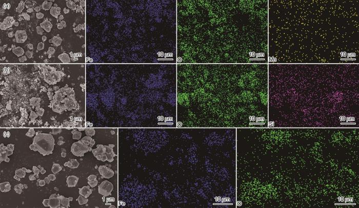
图4
不同管道腐蚀产物的SEM像及EDS谱
Fig.4
SEM images and EDS spectra of corrosion products from different pipes: (a) corrosion sample 1, (b) corrosion sample 2, (c) corrosion sample 3
图5红外光谱分析显示,1号样品(图5a)在3437.98 cm-1 (O—H)和1635.34 cm-1 (C=O)处有显著峰,分别表明存在水分/羟基铁氧化物及防腐层降解产物;1044.75 cm-1处为Si—O或P—O键,590.59 cm-1处为Fe—O键,说明含硅/磷组分及铁氧化物。2号样品(图5b)在3446.52 cm-1 (O—H)和1643.54 cm-1 (C=O)出现吸收峰,表明存在吸附水与降解羰基化合物;1388.53 cm-1处可能为碳酸根,1046.19 cm-1为Si—O或P—O键,587.70 cm-1处Fe-O峰表明腐蚀产物以铁氧化物为主。3号样品(图5c)在3450.99 cm-1(O—H)和1637.27 cm-1 (C=O)有吸收,反映防腐层降解及有机酸生成;1407.78和1052.46 cm-1处分别为碳酸盐和无机残留成分。整体结果显示所有样品均出现防腐层降解和以铁氧化物为主的腐蚀产物。
图5

图5
不同管道防腐层的红外光谱图
Fig.5
Infrared spectra of different pipe coatings: (a) corrosion sample 1, (b) corrosion sample 2, (c) corrosion sample 3
2.4 防腐层腐蚀机理分析及关键因子识别
图6为管道外防腐层腐蚀原因解析图。现场测得保护端与非保护端的通电电位分别为-1.196 V和-1.063 V,两端通电电位接近,推测管道绝缘接头的绝缘性失效。保护端管道施加阴极保护电流时,电流沿管壁经绝缘接头流入非保护端管道。在这种情况下,如果非保护端管道外防腐层本身存在防腐层漏点,或现场施工过程中损伤了外防腐层导致形成漏点,则可能导致管道外的腐蚀介质(如水分子和Cl-)通过防腐层渗透,进一步加剧腐蚀。
图6

图6
在阴极保护下的外防腐层的腐蚀原因分析
Fig.6
Corrosion cause analysis of external anti-corrosion coating under cathodic protection
当漏点区域的涂层发生水降解时,水分渗透涂层并与材料发生反应,削弱了涂层的保护能力。同时,水分作为介质携带Cl-和SO
3PE防腐层的腐蚀性能主要受土壤Cl-含量、环境温度及自身力学性能影响,这些因子在腐蚀机理中起关键作用。湿润环境中,水分渗透防腐层并与其发生反应,导致防腐层降解劣化;高Cl-浓度下,水分成为Cl-渗透的“载体”,加速侵蚀进程。浸泡温度升高会降低防腐层拉伸强度,高温加剧其分子运动,使其软化膨胀,削弱抗外力能力。防腐层起泡与水分渗透、内部膨胀及温度变化密切相关,水分易在防腐层裂缝、孔隙等缺陷处聚集,既可能引发化学反应,还可能导致内部气体或溶剂蒸发。
3 结论
(1) 带阴极保护的防腐层性能优于未保护的,证明阴极保护能有效延长3PE防腐层寿命;高温环境会降低防腐层性能,使其更易损坏或剥离,进而缩短使用寿命。防腐层力学性能与腐蚀情况存在关联,力学性能越差越易腐蚀,其中拉伸强度和断裂拉伸应变是主要影响因素。
(2) 保护端的Cl-浓度为2.99 mg/g,明显高于非保护端,但保护端的腐蚀程度仍较轻,这充分验证了阴极保护措施的有效性。
(3) 防腐层样品发生了降解且腐蚀产物以铁氧化物为主,其中相较于保护端,非保护端的腐蚀程度更为严重,这同样也可以证明阴极保护的有效性。
(4) 3PE防腐层的关键因子主要包含水分、Cl-含量、温度以及防腐层的拉伸强度。
参考文献
The study of detection technology and instrument of buried pipeline-coating defects
[A].
Coating property effects on guided wave attenuation in viscoelastic coated pipes
[J].
External polymeric pipeline coating failure modes
[J].
Field joint coating of pipelines-effect of soluble salt contamination on 2-layer heat shrink sleeve performance
[J].
– During offshore pipe-lay, pipe lengths with anticorrosion coating are welded together, and, to facilitate the welding process, the ends of the pipe remain uncoated. A wide range of field joint coating (FJC) types is available for coating this bare section, functioning in conjunction with the pipeline cathodic protection system to provide an anti-corrosion system or package. This paper aims to relate to two-layer type heat shrink sleeves (2LHSS), which commonly are used for FJC of concrete-weighted offshore pipelines where the sleeve typically is over-coated with a solid or foam type polyurethane “infill”. Similar sleeves also are used sometimes in exposed conditions on lines without concrete over-coating. The maximum allowable soluble salt contamination prior to application of high-performance coating systems can vary, depending upon the coating type, but typically has been set at 20 mg/m2 (de la Fuenteet al., 2006). The first layer of three-layer heat shrink sleeve (3LHSS) systems for pipeline FJC, liquid epoxy, falls into this category (ISO_21809-3:2008, 2008). In contrast, the 2LHSS system does not use a liquid epoxy first layer but relies instead on the bonding of a “mastic” layer directly to the pipe metal surface. The maximum acceptable concentration of salt contamination on prepared metal surfaces prior to the application of 2LHSS has been a subject of debate and was the focus of this study. International standards for FJC do not provide a maximum salt level. However, some companies have continued to specify low thresholds for the maximum allowable salt level for 2LHSS, which can result in expensive delays in production during offshore pipe-lay. In this study, salt contamination levels of up to 120 mg/m2 were found to have no effect on peeling performance after accelerated aging by hot water immersion. Furthermore, preparation for welding and the use of potable water during ultrasonic testing procedures prior to FJC, typically reduces the salt contamination level to below 50 mg/m2 providing a strong case for the deletion of salt contamination testing for 2LHSS.
Corrosion resistance of Fe-Al/Al2O3 duplex coating on pipeline steel X80 in simulated oil and gas well environment
[J].Corrosion resistant Fe – Al / Al 2 O 3 duplex coating for pipeline steel X80 was prepared by a combined treatment of low-temperature aluminizing and micro-arc oxidation (MAO). Phase composition and microstructure of mono-layer Fe – Al coating and Fe – Al / Al 2 O 3 duplex coating were studied by X-ray diffraction (XRD), scanning electron microscope (SEM) with energy dispersive spectrometer (EDS). Corrosion resistance of the coated pipeline steel X80 in a simulated oil and gas well condition was also investigated. Mono-layer Fe – Al coating consists of Fe 2 Al 5 and FeAl, which is a suitable transitional layer for the preparation of ceramic coating by MAO on the surface of pipeline steel X80. Under the same corrosion condition at 373 K for 168 h with 1 MPa CO 2 and 0.1 MPa H 2 S, corrosion weight loss rate of pipeline steel X80 with Fe – Al / Al 2 O 3 duplex coating decreased to 23% of original pipeline steel X80, which improved by 10% than that of pipeline steel X80 with mono-layer Fe – Al coating. It cannot find obvious cracks and pits on the corrosion surface of pipeline steel X80 with Fe – Al / Al 2 O 3 duplex coating.
An electrochemical method for evaluating the resistance to cathodic disbondment of anti-corrosion coatings on buried pipelines
[J]. J.
A new detecting technology for external anticorrosive coating defects of pipelines based on ultrasonic guided wave
[J].
Cause analysis and control measures of cracks in 3PE external anti-corrosion coating of oil and gas pipeline
[J].
油气管道3PE外防腐层产生裂纹原因分析及控制措施
[J].
Different vintage pipeline coating failure mechanisms and external corrosion conditions between liquids and gas transmission pipelines
[A].
Identification and analysis of SH wave detection signal for pipeline coating based on HHT
[A]. 2015 International Conference on Intelligent Transportation, Big Data and Smart City [C].
Calculation of the hydraulic characteristics of the protective coating used in trenchless technologies for the construction and renovation of pipelines to extend their service life
[J].
Evolution of external pipeline coatings for corrosion protection-a review
[J].External surfaces of pipelines are protected from corrosion by polymeric coatings that have evolved in the industry over the past 60 years, beginning with asphalt and then coal tar coatings, followed by polyethylene, epoxy, and urethane coatings. When a coating degrades or fails, the type of coating has an effect on the generation of environments that can cause corrosion and stress-corrosion cracking (SCC). In this paper, the types of coatings, laboratory performance, field performance, and the state-of-the-art of various pipeline coatings are reviewed.
Differential scanning calorimetry and electrochemical tests for the analysis of delamination of 3PE coatings
[J].
An overview of major methods for inspecting and monitoring external corrosion of on-shore transportation pipelines
[J].
Comparative analysis of domestic and international technical standards for 3PE coating repair of pipelines
[J].
国内外管道3PE防腐层修补技术标准对比分析
[J].
Effects of eva-hot melt adhesive polarity and rheology on 3PE modes
[J].
Stress corrosion cracking of X80 pipeline steel at coating defect in acidic soil
[J].The three-layer polyethylene (3PE or 3LPE) coatings have been widely used on long-distance high pressure transmission pipelines in China. The 3PE coating tends to remain high insulating after disbonding from pipelines, and block the function of cathoidc protection (CP), similar to PE tape coatings that caused stress corrosion cracking (SCC) failure of pipeline. Disbondment 3PE coatings have been reported worldwide. Because of the high integrity and dielectric strength of 3PE coatings, SCC under disbonded 3PE coating becomes an important issue for integrity management and operation of high pressure pipelines. A great deal of researches have been conducting over the past 20 years to reproduce SCC of high strength low alloy (HSLA) pipeline in laboratory. Most of these studies were conducted in bulk solution condition. The methodology neglects particularity of the thin-layer electrolyte under disbonded coating which has been identified as one of the primary environmental factors related to SCC. In this context, a research project has been initiated on this subject. The overall goal is to systematically investigate corrosion scenarios and mechanochemical interaction of HSLA pipeline steels under disbonded 3PE coating in different soil environments, particularly to further mechanistic understanding the initiation of SCC on pipelines under disbonded coating. In this work, SCC behavior of API X80 pipeline steel under disbonded coating with defect was investigated in acidic soil solution by a crevice cell specially designed for simulating coating disbondment. The crevice cell was equipped with a multi-sample loading frame, through which multi specimens in the crevice cell can be loaded simultaneously. Electrochemical impedance spectroscopy (EIS) was applied to characterize local electrochemical process of the tensile specimens. Local environment parameters (potential and pH) were monitored by microelectrodes. Surface morphology of the corrosion specimens indicate that corrosion intensity of X80 steel decreased over the distance from the opening. Intensive anodic dissolution and microcrack initiation were preferential at the opening defect, whereas corrosion was markedly mitigated under disbonded coating. CO2 content gradient is proposed for the special corrosion scenarios under coating disbondment.
酸性土壤中破损防腐层下X80管线钢的应力腐蚀行为
[J].设计加载阵列电极应力腐蚀实验装置, 针对我国典型的华南酸性红壤环境, 研究高强度低合金(HSLA) X80管线钢在破损防腐层(涂层)模拟缝隙下的应力腐蚀开裂(SCC)行为及影响因素, 采用电化学阻抗谱(EIS)监测加载电极的腐蚀电化学过程, 利用微电极监测防腐层剥离区局部电位和pH值变化, 探讨破损涂层下HSLA管线钢SCC行为和规律. 结果表明, 防腐层开放破损(漏点)处管线钢发生严重腐蚀: 不受力试样表面以阳极溶解占主导的均匀腐蚀为主, 而拉伸试样表面出现大量微裂纹和点蚀坑, 且沿试样划痕优先生长; 封闭的剥离区内部管线钢的腐蚀程度显著减缓. 同时, 对涂层破损点及剥离区深处管线钢的腐蚀现象和过程进行了讨论.
Circumferential shear horizontal guided wave crack inspection of 3PE-coated pipes based on a CNN
[J].
Gaussian process regression based inspection robot for predicting and locating pipeline anticorrosion coating defects
[J].
Assessment of corrosion behavior of steel in deep ocean
[J].
深海环境钢材腐蚀行为评价技术
[J].
Corrosion behavior of S420 steel in different marine zones
[J].
S420海工钢在不同海洋区带环境下的腐蚀行为研究
[J].
Low efficiency of cathodic protection in marine tidal corrosion of X80 steel in the presence of Pseudomonas sp
[J].
Quantitative research on signal of pipeline coating defect detection based on HHT
[A].
Simulation study on axial location identification of damage in layered pipeline structures based on damage index
[J].This study investigates the feasibility of identifying the axial position of circumferential defects in laminated pipeline structures based on damage indices. Wavelet packet decomposition is combined with damage indices, and the effects of dual defects with the same circumferential position but different axial positions, as well as dual defects with different circumferential and axial positions, on damage indices are separately studied. Our aim was to determine the potential to use damage indices to identify the axial position of circumferential defects in laminated pipeline structures. ABAQUS finite element analysis software was used to establish models of laminated pipeline structures with single defects and dual defects (with the same circumferential position but different axial positions, and with different circumferential and axial positions). The laminated pipeline structure was composed of a steel pipe (structural layer), a rigid polyurethane foam (insulation layer), and a high-density polyethylene (anticorrosion layer). The received sensing signals were averaged, and subjected to 5-level wavelet packet decomposition, to calculate the damage index values, which were then organized into a damage index matrix. Based on the trend of changes in the damage index matrix, the effects of variations in the number and circumferential position of the defects on the identification of the axial position of the damage were analyzed. The results indicate that the trend in damage index changes is influenced by the number of defects, and the increase in the circumferential distance between the second and the piezoelectric element sensor. This study found that when 1.7λ≤PD≤3.4λ, Idouble defect 90°<Isingle defect<Idouble defect 0°; when 3.7λ≤PD≤4λ, Idouble defect 90°<0.3<Idouble defect 0°<Isingle defect. This article demonstrates that the identification of the axial position of damage in laminated pipeline structures can be achieved using the damage index values in the damage index matrix. Additionally, this damage identification method overcomes the limitation of the wavelet packet’s inability to identify dual defects with relatively small relative axial distances. This provides new ideas and methods for finite element analysis in identifying the axial position of damage in laminated pipeline structures.


