Research Progress on Hydrogen Damage Behavior of Pipeline Steel and Welds for Transportation of Hydrogen-blended Natural Gas
BAI Yunlong1,2, LENG Bing3, WEI Boxin1,2,4, DONG Lijin5, YU Changkun1, XU Jin1,2, SUN Cheng,1,2
1.Liaoning Shenyang Soil and Atmosphere Corrosion of Material National Observation and Research Station, Institute of Metal Research, Chinese Academy of Sciences, Shenyang 110016, China
2.School of Materials Science and Engineering, University of Science and Technology of China, Shenyang 110016, China
3.Oil Production Technology Research Institute of China Petroleum Liaohe Oilfield Company, Panjin 110206, China
4.School of Mechanical and Aerospace Engineering, Nanyang Technological University, Singapore 639798, Republic of Singapore
5.School of New Energy and Material, Southwest Petroleum University, Chengdu 610500, China
To transfer the blend natural gas with hydrogen through the existing natural gas pipelines is currently one of the most economical and effective ways for hydrogen energy transportation. However, when pipelines in contact with hydrogen-enriched atmospheres, hydrogen atoms can permeate into the pipeline steels inducing hydrogen damages, which can severely threaten the safety of pipelines. Factors such as high-pressure, stress, and corrosive media during service may be involved to the damage of pipelines. Based on these issues, this paper summarizes the compatibility of pipeline steels with hydrogen, analyzes the adsorption and diffusion of hydrogen within the steels from the perspectives of hydrogen permeation behavior and testing methods. Additionally, it summarizes the forms and mechanisms of hydrogen damage in pipeline steels and welds of transportation of hydrogen-blended natural gas, in terms of the relevant influencing factors. The findings may provide a theoretical basis for the selection, design, and safe service of transporting hydrogen-blended natural gas pipelines, promoting the safe development of the hydrogen economy.
BAI Yunlong, LENG Bing, WEI Boxin, DONG Lijin, YU Changkun, XU Jin, SUN Cheng. Research Progress on Hydrogen Damage Behavior of Pipeline Steel and Welds for Transportation of Hydrogen-blended Natural Gas. Journal of Chinese Society for Corrosion and Protection[J], 2025, 45(2): 283-295 DOI:10.11902/1005.4537.2024.260
Fig.2
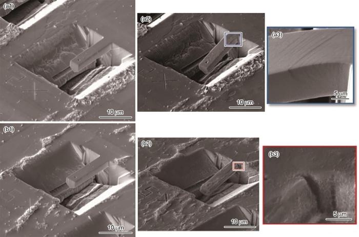
Selected SEM images of the without hydrogen (a) and hydrogen-charged (b) ferrite cantilevers deformed to 5000 nm displacement; (a2) and (b2) represent cross-sectional images of the marked areas in (a1) and (b1)[25]
Fig.3
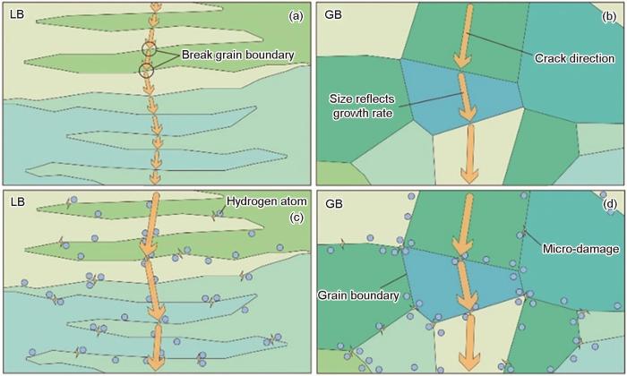
Schematic diagram the impact crack propagation in the CGHAZ obtaining mainly LB and GB, respectively, in the absence and presence of H atoms: (a) LB, no H, (b) GB, no H, (c) LB with H, (d) GB with H[31]
Fig.5
2D potential energy surface at local minima for hydrogen diffusion through the (111) surface (a), energy profile for hydrogen diffusion through the surface (b), diffusion pathway from the surface through towards the bulk (c), dotted line between stationary points is only a guide to the eye[34]
Fig.6
Cloud maps of hydrogen concentration distribution of the X80 steel pipewithout (a), and with residual stress before heat treatment (b) and after heat treatment (c)[35]
Fig.7
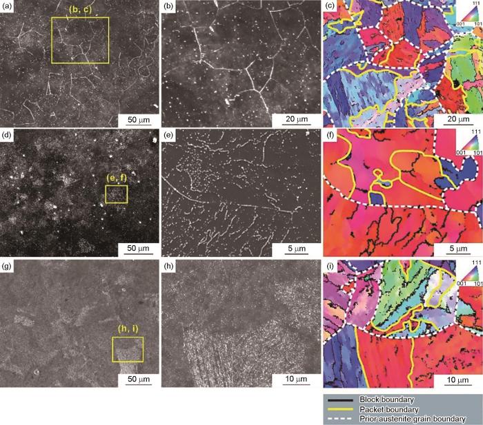
SEM images (a, b, d, e, g, h) and EBSD orientation maps (c, f, i) of the specimens after applying tensile stress of 300 MPa and hydrogen micro-print treatment[45]
Fig.8
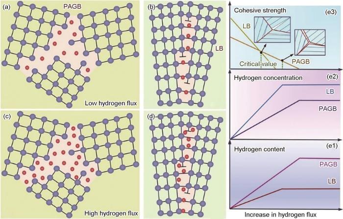
PAGB (a, c) and LB (b, d) at low (a, b) and high (c, d) hydrogen flux. (e) illustrates the evolution of hydrogen atom content (e1), hydrogen atom concentration (e2) and GB cohesive strength (e3) with increasing hydrogen flux[46]
Fig.11
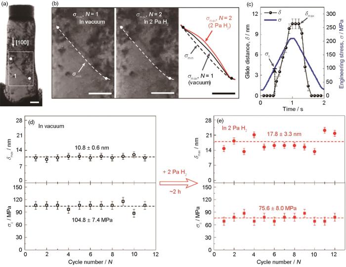
Bright-field transmission electron microscope image showing the pillar after a series of cyclic compression loading and unloading sessions (a), configurations of dislocation 1 at σmax in vacuum (N = 1) and in 2 Pa H2 (N = 2) (b), the loading engineering stress σ and the digitally tracked projected glide distance σ of dislocation 1 in a typical load cycle are shown as a function of time (c), the measured σmax and σc of dislocation 1 as a function of loading cycle number in vacuum (d) and in 2 Pa H2 (e)[64]
In order to achieve the goals of the “peak carbon dioxide emission and carbon neutrality”, it is essential to develop hydrogen energy. During the production, transportation, storage and use of hydrogen, hydrogen permeation is easy to occur and causes hydrogen damage to metal materials, which not only shortens the service life of pipelines and equipment, but also brings serious potential safety hazards. So it is of great significance to promote the development of permeated hydrogen detection techniques. Permeated hydrogen testing technology can be divided into indoor- and field-permeated hydrogen testing techniques. The indoor permeated hydrogen testing techniques include current method, hot/melt extraction, thermal desorption spectroscopy (TDS), hydrogen micro-contact printing (HMP), scanning Kelvin probe force microscopy (SKPFM), secondary ion mass spectroscopy (SIMS), atom probe tomography (APT) and neutron radiography (NRG). The field permeated hydrogen testing techniques include hydrogenochromic method, hydrogen flux method, hydrogen probe method, hydrogen sensor, as well as field Kelvin probe (FKP) technique. For the indoor testing, the principles and characteristics of several detection techniques were summarized and applicable scope was also introduced. The current method, hot/melt extraction and TDS are used to measure the average hydrogen concentration in materials, but none of the above methods have the ability of spatial resolution. The silver particles produced by the substitution reaction between Ag+ and H by HMP reflect the distribution and diffusion path of hydrogen, but it is not certain whether Fe participates in that. By continuously detecting the potential of a certain position, SKPFM can reveal the hydrogen enrichment and the dynamic process of diffusion in a specific position. However, when current/potential is applied on the sample surface, it will disturb the test results. Both SIMS and APT technology rely on mass spectrometry, and have spatial resolution but their measuring chamber need to be filled with deuterium to eliminate the influence of background hydrogen. NRG can judge the concentration and distribution of hydrogen by detecting the hydrogen intensity and bright area, but its spatial resolution can only reach micron level. For the field testing, the parameters of several testing equipment provided on the market are investigated in this article, while the principle, application scope, advantages and disadvantages of each method are also summarized. Finally, some suggestions are put forward for the future development of hydrogen permeation detection methods.
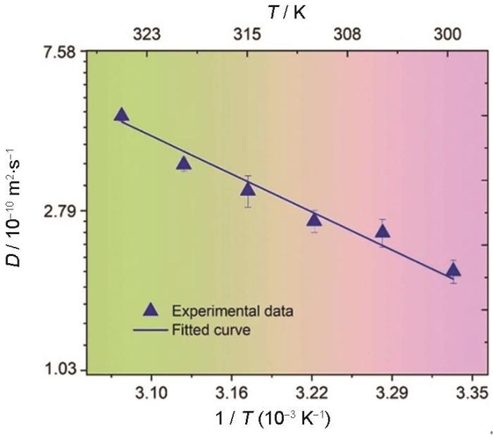
Investigations of temperature effects on hydrogen diffusion and hydrogen embrittlement of X80 pipeline steel under electrochemical hydrogen charging environment
AsadipoorM, Pourkamali AnarakiA, KadkhodapourJ, et al.
Macro- and microscale investigations of hydrogen embrittlement in X70 pipeline steel by in-situ and ex-situ hydrogen charging tensile tests and in-situ electrochemical micro-cantilever bending test
Welded joints of hydrogen-containing coal gas transmission pipelines are prone to hydrogen enrichment due to their severe microstructure inhomogeneity and residual stress in them, and thus lead to the decrease of plasticity and toughness. In order to investigate the effect of local hydrogen enrichment on the safety of hydrogen-containing coal gas transport pipelines, a three dimensional numerical simulation model was established to investigate the hydrogen diffusion behaviour considering the combined effect of microstructure inhomogeneity and residual stress in X80 spiral welded pipeline by using ABAQUS software. Results showed that both microstructure inhomogeneity and residual stress could lead to hydrogen diffusion. The distribution of hydrogen concentration in the pipeline was similar to that of hydrostatic stress distribution. That is, the higher the hydrostatic stress value, the higher the corresponding hydrogen concentration, indicating that the influence of residual stress on the hydrogen diffusion behaviour is greater than that of microstructure inhomogeneity. The enriched hydrogen concentration at the center region of the welded joint with the highest residual stress was 2.7 times higher than that without considering residual stress. Equivalent charging hydrogen pressure was put forward to reflect the degree of hydrogen enrichment in weld metal. Slow strain rate tension (SSRT) tests were subsequently performed on weld metal specimen at equivalent charging hydrogen pressure to investigate the effect of hydrogen enrichment on hydrogen embrittlement (HE) susceptibility. The SSRT tests performed in nitrogen gas and simulated coal gas were used for comparison. The HE index increased from 18.56% in simulated coal gas to 32.53% in equivalent charging hydrogen pressure, increasing by 75.27%. Therefore, the residual stress is a non-ignorable factor, because it could lead to hydrogen enrichment and could significantly influence HE susceptibility in welded joint. The determination of hydrogen enrichment in welded joint by using numerical simulation method is the basis to evaluate the safety of coal gas transmission pipeline.
Effects of Ni and Mn addition on critical crack tip opening displacement (CTOD) of weld-simulated heat-affected zones of three high-strength low-alloy (HSLA) steels
Combined effect of cathodic potential and sulfur species on calcareous deposition, hydrogen permeation, and hydrogen embrittlement of a low carbon bainite steel in artificial seawater
The difference between the chemical potential,μ_σ,of hydrogen atoms produ-cing a non-spherical symmetry strain in a solid sample under stress and that,μ_0corresponding to the state without stress has been studied.It is shown that μ_σ-μ_0=■=U,where σ_1——principal stress,■——strain component along thedirection of the principal stress,V——volume and U——interaction energy betweenthe strain field and external stress field.The hydrogen atoms producing the tetragonally symmetric strain are preferen-tially ordered in samples under stress.As a result,the variation of hydrogenconcentration with tensile stress σ will be different from that with compressive stressσ.For a general polycrystal the formulas are respectively■where C_t,C_p,C_0——hydrogen concentraiton under tensile stress,compressive stressand without stress respectively.Hence,ε_(11)/ε_(22)may be determined in terms of C_t/C_pwhich can be obtained by hydrogen permeation measurement.For example,according to Bockris's data,ε_(11)/ε_(22)=1.27 at temperature of 27℃ which impliesthat the strain field of hydrogen atoms in α-Fe is non-spherical symmetry.For a torsional stress τ,U=-0.55133Vτ(ε_(11)-ε_(22)).The interaction can resultin the enrichment of hydrogen atoms and hydrogen induced delayed crackingalong the planes inclined at an angle of α=45°to torsional axis,which was ob-served in pre-charged smooth torsional or type Ⅲ cracked specimens made of ultra-high strength steel.
A sequential coupling calculating method on hydrogen diffusion had been developed based on the finite element program-ABAQUS. Using this method, effect of welding residual stress on the hydrogen diffusion was numerically simulated for the as-weld condition and postweld heat treatment (PWHT) condition. The diffusion without the effect of stress was also taken into account and compared with those with stress. The results show that hydrogen will diffuse and accumulate in the higher stress region under the existence of welding residual stress gradient. A low hydrogen concentration valley exists near the heat-affected zone(HAZ), which is caused by the long-range diffusion of hydrogen to the high stress zone. After the PWHT, stress relaxation is obvious and the maximum stress is decreased about 50%, which influences the hydrogen diffusion and makes the hydrogen concentration be decreased about 40%. Therefore, decrease in the welding residual stress by PWHT can effectively reduce the hydrogen concentration in the weldment and the susceptibility of material to environment hydrogen cracking.
The synergistic action of HELP and HEDE mechanisms of hydrogen embrittlement in steels
[A]. Invited Talk-International Symposium: “HYDROGENIUS, I 2CNER and HydroMate Joint Research Symposium on HydrogenMaterials Interactions 2021”[C]. Fukuoka, Japen, 2021
In-depth understanding in the effect of hydrogen on microstructural evolution, mechanical properties and fracture micro-mechanisms of advanced high-strength steels welded joints
Investigations of temperature effects on hydrogen diffusion and hydrogen embrittlement of X80 pipeline steel under electrochemical hydrogen charging environment
Macro- and microscale investigations of hydrogen embrittlement in X70 pipeline steel by in-situ and ex-situ hydrogen charging tensile tests and in-situ electrochemical micro-cantilever bending test
Selected SEM images of the without hydrogen (a) and hydrogen-charged (b) ferrite cantilevers deformed to 5000 nm displacement; (a2) and (b2) represent cross-sectional images of the marked areas in (a1) and (b1)<sup>[<xref ref-type="bibr" rid="R25">25</xref>]</sup>Fig.2
Schematic diagram the impact crack propagation in the CGHAZ obtaining mainly LB and GB, respectively, in the absence and presence of H atoms: (a) LB, no H, (b) GB, no H, (c) LB with H, (d) GB with H<sup>[<xref ref-type="bibr" rid="R31">31</xref>]</sup>Fig.3<strong>2.2</strong> 理论模拟计算
Schematic diagram the impact crack propagation in the CGHAZ obtaining mainly LB and GB, respectively, in the absence and presence of H atoms: (a) LB, no H, (b) GB, no H, (c) LB with H, (d) GB with H<sup>[<xref ref-type="bibr" rid="R31">31</xref>]</sup>Fig.3<strong>2.2</strong> 理论模拟计算
... [31]Schematic diagram the impact crack propagation in the CGHAZ obtaining mainly LB and GB, respectively, in the absence and presence of H atoms: (a) LB, no H, (b) GB, no H, (c) LB with H, (d) GB with H<sup>[<xref ref-type="bibr" rid="R31">31</xref>]</sup>Fig.3<strong>2.2</strong> 理论模拟计算
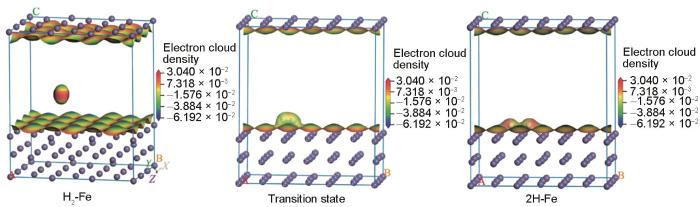
... [33]Electronic cloud density distribution changes during H<sub>2</sub> adsorption and dissociation on the Fe metal (110) surface<sup>[<xref ref-type="bibr" rid="R33">33</xref>]</sup>Fig.4
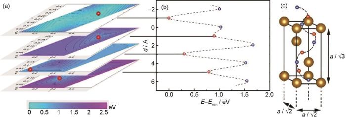
2D potential energy surface at local minima for hydrogen diffusion through the (111) surface (a), energy profile for hydrogen diffusion through the surface (b), diffusion pathway from the surface through towards the bulk (c), dotted line between stationary points is only a guide to the eye<sup>[<xref ref-type="bibr" rid="R34">34</xref>]</sup>Fig.5
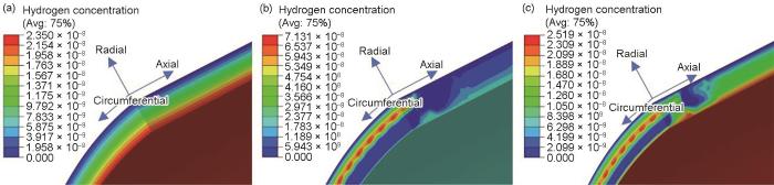
Cloud maps of hydrogen concentration distribution of the X80 steel pipewithout (a), and with residual stress before heat treatment (b) and after heat treatment (c)<sup>[<xref ref-type="bibr" rid="R35">35</xref>]</sup>Fig.6
2D potential energy surface at local minima for hydrogen diffusion through the (111) surface (a), energy profile for hydrogen diffusion through the surface (b), diffusion pathway from the surface through towards the bulk (c), dotted line between stationary points is only a guide to the eye<sup>[<xref ref-type="bibr" rid="R34">34</xref>]</sup>Fig.5
Cloud maps of hydrogen concentration distribution of the X80 steel pipewithout (a), and with residual stress before heat treatment (b) and after heat treatment (c)<sup>[<xref ref-type="bibr" rid="R35">35</xref>]</sup>Fig.6
... [33]Electronic cloud density distribution changes during H<sub>2</sub> adsorption and dissociation on the Fe metal (110) surface<sup>[<xref ref-type="bibr" rid="R33">33</xref>]</sup>Fig.4
2D potential energy surface at local minima for hydrogen diffusion through the (111) surface (a), energy profile for hydrogen diffusion through the surface (b), diffusion pathway from the surface through towards the bulk (c), dotted line between stationary points is only a guide to the eye<sup>[<xref ref-type="bibr" rid="R34">34</xref>]</sup>Fig.5
Cloud maps of hydrogen concentration distribution of the X80 steel pipewithout (a), and with residual stress before heat treatment (b) and after heat treatment (c)<sup>[<xref ref-type="bibr" rid="R35">35</xref>]</sup>Fig.6
... [34]2D potential energy surface at local minima for hydrogen diffusion through the (111) surface (a), energy profile for hydrogen diffusion through the surface (b), diffusion pathway from the surface through towards the bulk (c), dotted line between stationary points is only a guide to the eye<sup>[<xref ref-type="bibr" rid="R34">34</xref>]</sup>Fig.5
Cloud maps of hydrogen concentration distribution of the X80 steel pipewithout (a), and with residual stress before heat treatment (b) and after heat treatment (c)<sup>[<xref ref-type="bibr" rid="R35">35</xref>]</sup>Fig.6
Cloud maps of hydrogen concentration distribution of the X80 steel pipewithout (a), and with residual stress before heat treatment (b) and after heat treatment (c)<sup>[<xref ref-type="bibr" rid="R35">35</xref>]</sup>Fig.6
... [35]Cloud maps of hydrogen concentration distribution of the X80 steel pipewithout (a), and with residual stress before heat treatment (b) and after heat treatment (c)<sup>[<xref ref-type="bibr" rid="R35">35</xref>]</sup>Fig.6
... [35]Cloud maps of hydrogen concentration distribution of the X80 steel pipewithout (a), and with residual stress before heat treatment (b) and after heat treatment (c)<sup>[<xref ref-type="bibr" rid="R35">35</xref>]</sup>Fig.6
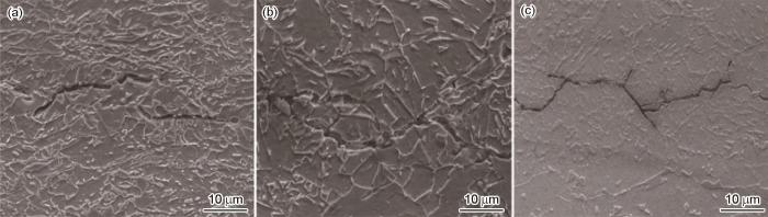
SEM images of the propagation path of HIC cracks in X100 pipeline steel: (a) original, (b) furnace cooling, (c) wind cooling<sup>[<xref ref-type="bibr" rid="R48">48</xref>]</sup>Fig.10<strong>3.3</strong> 管线钢强度等级
SEM images of the propagation path of HIC cracks in X100 pipeline steel: (a) original, (b) furnace cooling, (c) wind cooling<sup>[<xref ref-type="bibr" rid="R48">48</xref>]</sup>Fig.10<strong>3.3</strong> 管线钢强度等级
SEM images of the propagation path of HIC cracks in X100 pipeline steel: (a) original, (b) furnace cooling, (c) wind cooling<sup>[<xref ref-type="bibr" rid="R48">48</xref>]</sup>Fig.10<strong>3.3</strong> 管线钢强度等级
SEM images of the propagation path of HIC cracks in X100 pipeline steel: (a) original, (b) furnace cooling, (c) wind cooling<sup>[<xref ref-type="bibr" rid="R48">48</xref>]</sup>Fig.10<strong>3.3</strong> 管线钢强度等级
Effects of Ni and Mn addition on critical crack tip opening displacement (CTOD) of weld-simulated heat-affected zones of three high-strength low-alloy (HSLA) steels
... [45]SEM images (a, b, d, e, g, h) and EBSD orientation maps (c, f, i) of the specimens after applying tensile stress of 300 MPa and hydrogen micro-print treatment<sup>[<xref ref-type="bibr" rid="R45">45</xref>]</sup>Fig.7
PAGB (a, c) and LB (b, d) at low (a, b) and high (c, d) hydrogen flux. (e) illustrates the evolution of hydrogen atom content (e1), hydrogen atom concentration (e2) and GB cohesive strength (e3) with increasing hydrogen flux<sup>[<xref ref-type="bibr" rid="R46">46</xref>]</sup>Fig.8
SEM images of the propagation path of HIC cracks in X100 pipeline steel: (a) original, (b) furnace cooling, (c) wind cooling<sup>[<xref ref-type="bibr" rid="R48">48</xref>]</sup>Fig.10<strong>3.3</strong> 管线钢强度等级
Combined effect of cathodic potential and sulfur species on calcareous deposition, hydrogen permeation, and hydrogen embrittlement of a low carbon bainite steel in artificial seawater
... [46]PAGB (a, c) and LB (b, d) at low (a, b) and high (c, d) hydrogen flux. (e) illustrates the evolution of hydrogen atom content (e1), hydrogen atom concentration (e2) and GB cohesive strength (e3) with increasing hydrogen flux<sup>[<xref ref-type="bibr" rid="R46">46</xref>]</sup>Fig.8
SEM images of the propagation path of HIC cracks in X100 pipeline steel: (a) original, (b) furnace cooling, (c) wind cooling<sup>[<xref ref-type="bibr" rid="R48">48</xref>]</sup>Fig.10<strong>3.3</strong> 管线钢强度等级
SEM images of the propagation path of HIC cracks in X100 pipeline steel: (a) original, (b) furnace cooling, (c) wind cooling<sup>[<xref ref-type="bibr" rid="R48">48</xref>]</sup>Fig.10<strong>3.3</strong> 管线钢强度等级
... [48]SEM images of the propagation path of HIC cracks in X100 pipeline steel: (a) original, (b) furnace cooling, (c) wind cooling<sup>[<xref ref-type="bibr" rid="R48">48</xref>]</sup>Fig.10<strong>3.3</strong> 管线钢强度等级
... [48]SEM images of the propagation path of HIC cracks in X100 pipeline steel: (a) original, (b) furnace cooling, (c) wind cooling<sup>[<xref ref-type="bibr" rid="R48">48</xref>]</sup>Fig.10<strong>3.3</strong> 管线钢强度等级
Bright-field transmission electron microscope image showing the pillar after a series of cyclic compression loading and unloading sessions (a), configurations of dislocation 1 at σmax in vacuum (<i>N</i> = 1) and in 2 Pa H<sub>2</sub> (<i>N</i> = 2) (b), the loading engineering stress <i>σ</i> and the digitally tracked projected glide distance <i>σ</i> of dislocation 1 in a typical load cycle are shown as a function of time (c), the measured <i>σ</i><sub>max</sub> and <i>σ</i><sub>c</sub> of dislocation 1 as a function of loading cycle number in vacuum (d) and in 2 Pa H<sub>2</sub> (e)<sup>[<xref ref-type="bibr" rid="R64">64</xref>]</sup>Fig.114.3 AIDE
In-depth understanding in the effect of hydrogen on microstructural evolution, mechanical properties and fracture micro-mechanisms of advanced high-strength steels welded joints


